Information injection-pump assembly
BOSCH
9 400 610 925
9400610925
ZEXEL
106673-7221
1066737221
MITSUBISHI
ME158092
me158092

Rating:
Service parts 106673-7221 INJECTION-PUMP ASSEMBLY:
1.
_
7.
COUPLING PLATE
8.
_
9.
_
11.
Nozzle and Holder
ME158153
12.
Open Pre:MPa(Kqf/cm2)
17.7{180}/21.6{220}
14.
NOZZLE
Include in #1:
106673-7221
as INJECTION-PUMP ASSEMBLY
Cross reference number
BOSCH
9 400 610 925
9400610925
ZEXEL
106673-7221
1066737221
MITSUBISHI
ME158092
me158092
Zexel num
Bosch num
Firm num
Name
106673-7221
9 400 610 925
ME158092 MITSUBISHI
INJECTION-PUMP ASSEMBLY
6D24T K 14CA INJECTION PUMP ASSY PE6P,6PD PE
6D24T K 14CA INJECTION PUMP ASSY PE6P,6PD PE
Calibration Data:
Adjustment conditions
Test oil
1404 Test oil ISO4113 or {SAEJ967d}
1404 Test oil ISO4113 or {SAEJ967d}
Test oil temperature
degC
40
40
45
Nozzle and nozzle holder
105780-8140
Bosch type code
EF8511/9A
Nozzle
105780-0000
Bosch type code
DN12SD12T
Nozzle holder
105780-2080
Bosch type code
EF8511/9
Opening pressure
MPa
17.2
Opening pressure
kgf/cm2
175
Injection pipe
Outer diameter - inner diameter - length (mm) mm 8-3-600
Outer diameter - inner diameter - length (mm) mm 8-3-600
Overflow valve
131424-4620
Overflow valve opening pressure
kPa
255
221
289
Overflow valve opening pressure
kgf/cm2
2.6
2.25
2.95
Tester oil delivery pressure
kPa
157
157
157
Tester oil delivery pressure
kgf/cm2
1.6
1.6
1.6
Direction of rotation (viewed from drive side)
Right R
Right R
Injection timing adjustment
Direction of rotation (viewed from drive side)
Right R
Right R
Injection order
1-5-3-6-
2-4
Pre-stroke
mm
4.8
4.75
4.85
Beginning of injection position
Governor side NO.1
Governor side NO.1
Difference between angles 1
Cal 1-5 deg. 60 59.5 60.5
Cal 1-5 deg. 60 59.5 60.5
Difference between angles 2
Cal 1-3 deg. 120 119.5 120.5
Cal 1-3 deg. 120 119.5 120.5
Difference between angles 3
Cal 1-6 deg. 180 179.5 180.5
Cal 1-6 deg. 180 179.5 180.5
Difference between angles 4
Cyl.1-2 deg. 240 239.5 240.5
Cyl.1-2 deg. 240 239.5 240.5
Difference between angles 5
Cal 1-4 deg. 300 299.5 300.5
Cal 1-4 deg. 300 299.5 300.5
Injection quantity adjustment
Adjusting point
A
Rack position
9.6
Pump speed
r/min
1000
1000
1000
Average injection quantity
mm3/st.
135.5
132.5
138.5
Max. variation between cylinders
%
0
-3
3
Basic
*
Fixing the lever
*
Injection quantity adjustment_02
Adjusting point
C
Rack position
6.9+-0.5
Pump speed
r/min
550
550
550
Average injection quantity
mm3/st.
65
62.4
67.6
Fixing the rack
*
Injection quantity adjustment_03
Adjusting point
D
Rack position
5.5+-0.5
Pump speed
r/min
350
350
350
Average injection quantity
mm3/st.
17.5
14.9
20.1
Max. variation between cylinders
%
0
-15
15
Fixing the rack
*
Injection quantity adjustment_04
Adjusting point
E
Rack position
-
Pump speed
r/min
100
100
100
Average injection quantity
mm3/st.
135
125
145
Fixing the lever
*
Rack limit
*
Timer adjustment
Pump speed
r/min
0
Advance angle
deg.
2.5
2
3
Timer adjustment_02
Pump speed
r/min
300
Advance angle
deg.
2.5
2
3
Remarks
Start
Start
Timer adjustment_03
Pump speed
r/min
-
Advance angle
deg.
0
0
0
Remarks
Measure the actual speed, stop
Measure the actual speed, stop
Test data Ex:
Governor adjustment
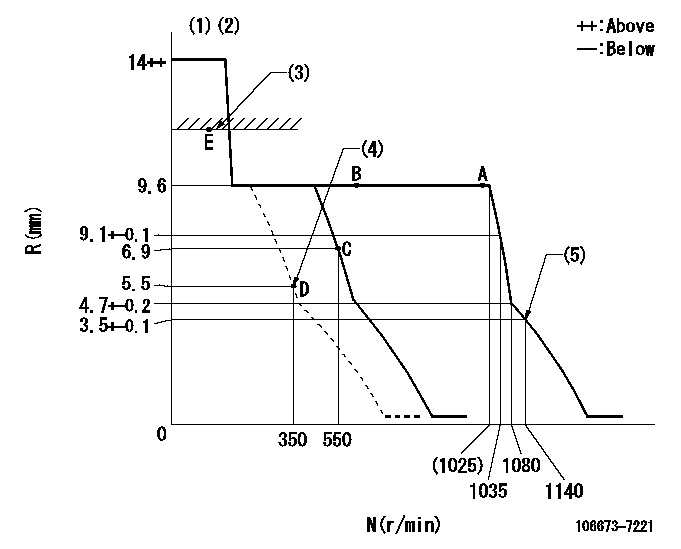
N:Pump speed
R:Rack position (mm)
(1)Target notch: K
(2)Tolerance for racks not indicated: +-0.05mm.
(3)RACK LIMIT
(4)Set at delivery
(5)Set idle sub-spring
----------
K=11
----------
----------
K=11
----------
Speed control lever angle
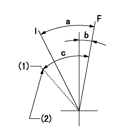
F:Full speed
I:Idle
(1)Set at delivery
(2)Stopper bolt setting
----------
----------
a=20deg+-5deg b=8deg+-5deg c=27deg+-5deg
----------
----------
a=20deg+-5deg b=8deg+-5deg c=27deg+-5deg
Stop lever angle
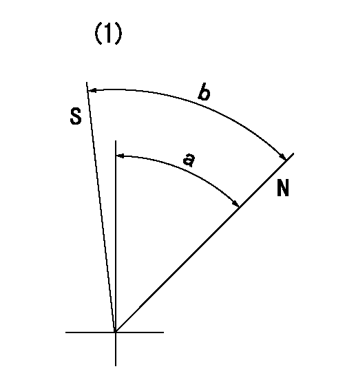
N:Pump normal
S:Stop the pump.
(1)No return spring
----------
----------
a=48.5deg+-5deg b=53deg+-5deg
----------
----------
a=48.5deg+-5deg b=53deg+-5deg
Timing setting

(1)Pump vertical direction
(2)Coupling's key groove position at No 1 cylinder's beginning of injection
(3)B.T.D.C.: aa
(4)-
----------
aa=12deg
----------
a=(6deg)
----------
aa=12deg
----------
a=(6deg)
Information:
Start By:a. remove valve covers
Typical Example1. Use Tool (A) to loosen the nuts and remove fuel lines (2).2. Disconnect fuel lines (1) from the valve cover base adapters.
Put protection caps (5F-2807) and plugs (2F-2990) on the fuel line openings to keep dirt and foreign material out of the fuel system.
3. Remove locks (3) and fuel line adapters (4) from the valve cover bases for clearance to remove the rocker shaft bolts. 4. Remove bolts (5) and rocker shaft assemblies (6) from the cylinder head. 5. Remove push rods (7) from the cylinder heads.6. Put identification on each valve bridge as to its location. Remove valve bridges (8) from the cylinder heads.Install Rocker Shaft Assemblies
1. Put clean engine oil on the bridge dowels, push rods (2) and inside bridges (1). Install bridges (1) and push rods (2) in the correct positions. 2. Push straight down on the top contact surface of valve bridge (1) with a force of 4 to 45 N (1 to 10 lb). Turn the adjustment screw clockwise until contact is made with the valve stem. Turn the adjustment screw 20 to 30 degrees more to keep bridge (1) straight on the dowel. Hold the adjustment screw in this position and tighten the locknut to a torque of 28 4 N m (22 3 lb ft). 3. Put rocker shaft assembly (3) in position on the cylinder head. Make sure the adjustment screws in the rocker arms are correctly engaged with the push rods. 4. Put clean engine oil on the threads of the bolts and install the bolts to hold rocker shaft assembly. Tighten the bolts as follows:a. Tighten bolts 1 through 6 in number sequence shown to a torque of 270 25 N m (200 20 lb ft).b. Tighten bolts 1 through 6 in number sequence shown to a torque of 447 20 N m (330 15 lb ft).c. Tighten bolts 1 through 6 in number sequence shown again to a torque of 447 20 N m (330 15 lb ft). 5. Put clean engine oil on the O-ring seals and install fuel line adapters (5), the washers, spaces, locks and nuts (4). Tighten nuts (4) to a torque of 14 3 N m (10 2 lb ft) 6. Install fuel lines (7) and connect fuel lines (6) to the fuel line adapters. Use Tool (A) and tighten the nuts for fuel lines (7). Tighten all fuel line nuts to a torque of 40 7 N m (30 5 lb ft).7. Make an adjustment of the valves to have a clearance of 0.38 mm (.015 in) for intake and 0.76 mm (.030 in) for exhaust. See Valve Clearance Setting in Testing And Adjusting.End By:a. install valve covers Disassemble Rocker Shaft Assemblies
Start By:a. remove rocker shaft assemblies 1. Remove retainer (1) from the end of the shaft.2. Remove the washers and rocker arm (2). 3. Use Tool (A) to remove the pin that
Have questions with 106673-7221?
Group cross 106673-7221 ZEXEL
Mitsubishi
Mitsubishi
Mitsubishi
106673-7221
9 400 610 925
ME158092
INJECTION-PUMP ASSEMBLY
6D24T
6D24T