Information injection-pump assembly
ZEXEL
106673-7190
1066737190

Rating:
Cross reference number
ZEXEL
106673-7190
1066737190
Zexel num
Bosch num
Firm num
Name
106673-7190
INJECTION-PUMP ASSEMBLY
Calibration Data:
Adjustment conditions
Test oil
1404 Test oil ISO4113 or {SAEJ967d}
1404 Test oil ISO4113 or {SAEJ967d}
Test oil temperature
degC
40
40
45
Nozzle and nozzle holder
105780-8140
Bosch type code
EF8511/9A
Nozzle
105780-0000
Bosch type code
DN12SD12T
Nozzle holder
105780-2080
Bosch type code
EF8511/9
Opening pressure
MPa
17.2
Opening pressure
kgf/cm2
175
Injection pipe
Outer diameter - inner diameter - length (mm) mm 8-3-600
Outer diameter - inner diameter - length (mm) mm 8-3-600
Overflow valve
131424-4620
Overflow valve opening pressure
kPa
255
221
289
Overflow valve opening pressure
kgf/cm2
2.6
2.25
2.95
Tester oil delivery pressure
kPa
157
157
157
Tester oil delivery pressure
kgf/cm2
1.6
1.6
1.6
Direction of rotation (viewed from drive side)
Right R
Right R
Injection timing adjustment
Direction of rotation (viewed from drive side)
Right R
Right R
Injection order
1-5-3-6-
2-4
Pre-stroke
mm
4.8
4.75
4.85
Beginning of injection position
Governor side NO.1
Governor side NO.1
Difference between angles 1
Cal 1-5 deg. 60 59.5 60.5
Cal 1-5 deg. 60 59.5 60.5
Difference between angles 2
Cal 1-3 deg. 120 119.5 120.5
Cal 1-3 deg. 120 119.5 120.5
Difference between angles 3
Cal 1-6 deg. 180 179.5 180.5
Cal 1-6 deg. 180 179.5 180.5
Difference between angles 4
Cyl.1-2 deg. 240 239.5 240.5
Cyl.1-2 deg. 240 239.5 240.5
Difference between angles 5
Cal 1-4 deg. 300 299.5 300.5
Cal 1-4 deg. 300 299.5 300.5
Injection quantity adjustment
Adjusting point
A
Rack position
9
Pump speed
r/min
1000
1000
1000
Average injection quantity
mm3/st.
149
146
152
Max. variation between cylinders
%
0
-3
3
Basic
*
Fixing the lever
*
Boost pressure
kPa
40
40
Boost pressure
mmHg
300
300
Injection quantity adjustment_02
Adjusting point
B
Rack position
4.7+-0.5
Pump speed
r/min
400
400
400
Average injection quantity
mm3/st.
8
5.4
10.6
Max. variation between cylinders
%
0
-15
15
Fixing the rack
*
Boost pressure
kPa
0
0
0
Boost pressure
mmHg
0
0
0
Injection quantity adjustment_03
Adjusting point
D
Rack position
-
Pump speed
r/min
100
100
100
Average injection quantity
mm3/st.
125
105
145
Fixing the lever
*
Boost pressure
kPa
0
0
0
Boost pressure
mmHg
0
0
0
Rack limit
*
Boost compensator adjustment
Pump speed
r/min
600
600
600
Rack position
R1-1.2
Boost pressure
kPa
6.7
4
9.4
Boost pressure
mmHg
50
30
70
Boost compensator adjustment_02
Pump speed
r/min
600
600
600
Rack position
R1(9)
Boost pressure
kPa
26.7
20
33.4
Boost pressure
mmHg
200
150
250
Timer adjustment
Pump speed
r/min
825--
Advance angle
deg.
0
0
0
Remarks
Start
Start
Timer adjustment_02
Pump speed
r/min
775
Advance angle
deg.
0.5
Timer adjustment_03
Pump speed
r/min
975
Advance angle
deg.
1
0.5
1.5
Remarks
Finish
Finish
Test data Ex:
Governor adjustment
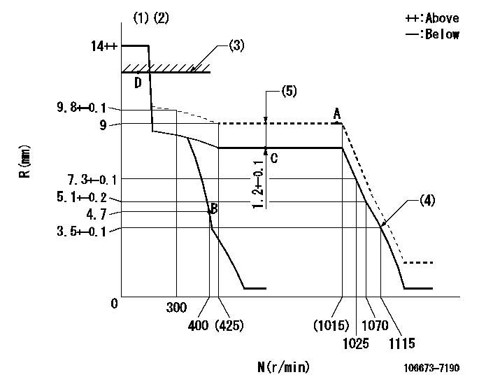
N:Pump speed
R:Rack position (mm)
(1)Target notch: K
(2)Tolerance for racks not indicated: +-0.05mm.
(3)RACK LIMIT
(4)Set idle sub-spring
(5)Boost compensator stroke
----------
K=13
----------
----------
K=13
----------
Speed control lever angle

F:Full speed
I:Idle
(1)Stopper bolt setting
----------
----------
a=20deg+-5deg b=6deg+-5deg
----------
----------
a=20deg+-5deg b=6deg+-5deg
Stop lever angle
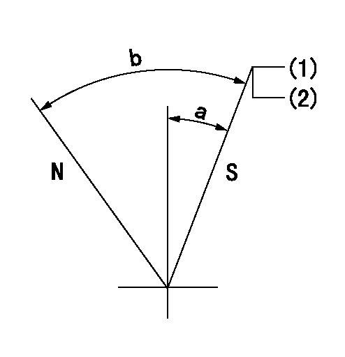
N:Pump normal
S:Stop the pump.
(1)Pump speed aa and rack position bb (to be sealed at delivery)
(2)Stopper bolt setting
----------
aa=0r/min bb=1-0.5mm
----------
a=35deg+-5deg b=70deg+-5deg
----------
aa=0r/min bb=1-0.5mm
----------
a=35deg+-5deg b=70deg+-5deg
Timing setting

(1)Pump vertical direction
(2)Coupling's key groove position at No 1 cylinder's beginning of injection
(3)B.T.D.C.: aa
(4)-
----------
aa=13deg
----------
a=(7deg)
----------
aa=13deg
----------
a=(7deg)
Information:
14. Put clean engine oil on the camshaft bearings and on camshaft (21). Install camshaft as shown. 15. Install camshaft gear (22) and retainer (23). Install the three bolts. 16. Put clean engine oil on lifters (25). Install lifters (25) and spacers (24) for each of the injection pumps. Be sure the lifters and spacers are put in their original location. 17. Put clean engine oil on the left and right fuel racks. Install left rack in the pump housing with the groove in the rack engaged with the tab of the rack bearing. Install right rack (26) with the groove in the rack engaged with the tab of the rack bearing. 18. Install dowel (27) in the pump housing until it is extended 12.2 0.5 mm (.48 .02 in) from the surface of the pump housing.19. Install link (29) and bracket assembly (30). Install bolt (28). Be careful so bracket (30) does not turn as bolt (28) is tightened. 20. Install Tool (E) in the injection pump housing to hold the racks in the center (zero) position.21. Put the space in gear segment (32) in alignment with the groove in pump barrel (31). Put the injection pump straight down into the housing bore with the space in gear segment (32) engaged with the pin in the lifter and the groove in barrel (31) engaged with the dowel in the pump housing. Use Tool (F) to install the pump. 22. Install seal (33) and bushing (34) in the pump housing bore. If the injection pump is in the correct position, bushing (34) will turn into the threads of the pump housing with the fingers until it is even with the housing.23. Tighten bushings (34) to a torque of 205 14 N m (150 10 lb ft) with Tool (G). 24. Install a felt washer (35) and protection caps for each injection pump. For more detail see the topic "Install Fuel Injection Pumps" in this module. 25. Heat gear (36) to a maximum temperature of 232°C (450°F) and install it on the shaft. 26. Install bearing in housing (37) with Tooling (C). 27. Install shaft and gear assembly (40) in fuel injection housing. Install gasket (39) on housing. Install small cover (38). Install housing (37) on fuel injection housing with the bolts that hold it. 28. Install fuel transfer pump (41) in housing (37) with the bolts that hold it. 29. If replacement of the dowels (43) in the governor plate is necessary, see illustration A42792P1 for correct installation dimensions. 30. Install bearing (42) for drive gear with Tooling (C) until it is 0.51 mm (.020 in) from the top surface of the governor plate. 31. Install drive gear (44), install ring (45) with Tool (H). 32. Install O-ring seals (47) on cylinder (46). 33. Install cylinder (46) in governor plate with the notch in the cylinder in alignment with the bolt hole in the governor plate. 34. Install O-ring seal (49) on sleeve (51).
Have questions with 106673-7190?
Group cross 106673-7190 ZEXEL
Mitsubishi
Mitsubishi
Mitsubishi
Mitsubishi
106673-7190
INJECTION-PUMP ASSEMBLY