Information injection-pump assembly
BOSCH
9 400 617 329
9400617329
ZEXEL
106673-7150
1066737150
MITSUBISHI
ME151542
me151542
Rating:
Cross reference number
BOSCH
9 400 617 329
9400617329
ZEXEL
106673-7150
1066737150
MITSUBISHI
ME151542
me151542
Zexel num
Bosch num
Firm num
Name
106673-7150
9 400 617 329
ME151542 MITSUBISHI
INJECTION-PUMP ASSEMBLY
6D22T3 * K 14CA INJECTION PUMP ASSY PE6P,6PD PE
6D22T3 * K 14CA INJECTION PUMP ASSY PE6P,6PD PE
Calibration Data:
Adjustment conditions
Test oil
1404 Test oil ISO4113 or {SAEJ967d}
1404 Test oil ISO4113 or {SAEJ967d}
Test oil temperature
degC
40
40
45
Nozzle and nozzle holder
105780-8140
Bosch type code
EF8511/9A
Nozzle
105780-0000
Bosch type code
DN12SD12T
Nozzle holder
105780-2080
Bosch type code
EF8511/9
Opening pressure
MPa
17.2
Opening pressure
kgf/cm2
175
Injection pipe
Outer diameter - inner diameter - length (mm) mm 8-3-600
Outer diameter - inner diameter - length (mm) mm 8-3-600
Overflow valve
131424-4620
Overflow valve opening pressure
kPa
255
221
289
Overflow valve opening pressure
kgf/cm2
2.6
2.25
2.95
Tester oil delivery pressure
kPa
157
157
157
Tester oil delivery pressure
kgf/cm2
1.6
1.6
1.6
Direction of rotation (viewed from drive side)
Right R
Right R
Injection timing adjustment
Direction of rotation (viewed from drive side)
Right R
Right R
Injection order
1-5-3-6-
2-4
Pre-stroke
mm
4.8
4.75
4.85
Beginning of injection position
Governor side NO.1
Governor side NO.1
Difference between angles 1
Cal 1-5 deg. 60 59.5 60.5
Cal 1-5 deg. 60 59.5 60.5
Difference between angles 2
Cal 1-3 deg. 120 119.5 120.5
Cal 1-3 deg. 120 119.5 120.5
Difference between angles 3
Cal 1-6 deg. 180 179.5 180.5
Cal 1-6 deg. 180 179.5 180.5
Difference between angles 4
Cyl.1-2 deg. 240 239.5 240.5
Cyl.1-2 deg. 240 239.5 240.5
Difference between angles 5
Cal 1-4 deg. 300 299.5 300.5
Cal 1-4 deg. 300 299.5 300.5
Injection quantity adjustment
Adjusting point
-
Rack position
10.3
Pump speed
r/min
650
650
650
Each cylinder's injection qty
mm3/st.
170.5
166.2
174.8
Basic
*
Fixing the rack
*
Standard for adjustment of the maximum variation between cylinders
*
Injection quantity adjustment_02
Adjusting point
F
Rack position
4.6+-0.5
Pump speed
r/min
500
500
500
Each cylinder's injection qty
mm3/st.
10
8.8
11.2
Fixing the rack
*
Standard for adjustment of the maximum variation between cylinders
*
Injection quantity adjustment_03
Adjusting point
A
Rack position
R1(10.3)
Pump speed
r/min
650
650
650
Average injection quantity
mm3/st.
170.5
169.5
171.5
Basic
*
Fixing the lever
*
Boost pressure
kPa
45.3
45.3
Boost pressure
mmHg
340
340
Injection quantity adjustment_04
Adjusting point
B
Rack position
R2(R1-1)
Pump speed
r/min
1075
1075
1075
Average injection quantity
mm3/st.
161
156.9
165.1
Difference in delivery
mm3/st.
8.2
8.2
8.2
Fixing the lever
*
Boost pressure
kPa
45.3
45.3
Boost pressure
mmHg
340
340
Injection quantity adjustment_05
Adjusting point
D
Rack position
R3(R1-2.
4)
Pump speed
r/min
500
500
500
Average injection quantity
mm3/st.
117
115
119
Fixing the lever
*
Boost pressure
kPa
0
0
0
Boost pressure
mmHg
0
0
0
Injection quantity adjustment_06
Adjusting point
C
Rack position
5.3+-0.5
Pump speed
r/min
225
225
225
Each cylinder's injection qty
mm3/st.
15
13.2
16.8
Fixing the rack
*
Boost pressure
kPa
0
0
0
Boost pressure
mmHg
0
0
0
Remarks
(check)
(check)
Injection quantity adjustment_07
Adjusting point
E
Rack position
-
Pump speed
r/min
100
100
100
Average injection quantity
mm3/st.
85
65
105
Fixing the lever
*
Boost pressure
kPa
0
0
0
Boost pressure
mmHg
0
0
0
Injection quantity adjustment_08
Adjusting point
F
Rack position
-
Pump speed
r/min
100
100
100
Average injection quantity
mm3/st.
160
150
170
Fixing the lever
*
Boost pressure
kPa
80
80
Boost pressure
mmHg
600
600
Rack limit
*
Boost compensator adjustment
Pump speed
r/min
600
600
600
Rack position
R3(R1-2.
4)
Boost pressure
kPa
3.3
3.3
5.3
Boost pressure
mmHg
25
25
40
Boost compensator adjustment_02
Pump speed
r/min
600
600
600
Rack position
R1-0.1
Boost pressure
kPa
21.3
20
22.6
Boost pressure
mmHg
160
150
170
Boost compensator adjustment_03
Pump speed
r/min
600
600
600
Rack position
(10.4)
Boost pressure
kPa
32
32
32
Boost pressure
mmHg
240
240
240
Timer adjustment
Pump speed
r/min
900--
Advance angle
deg.
0
0
0
Remarks
Start
Start
Timer adjustment_02
Pump speed
r/min
850
Advance angle
deg.
0.5
Timer adjustment_03
Pump speed
r/min
1075
Remarks
Measure the actual advance angle.
Measure the actual advance angle.
Timer adjustment_04
Pump speed
r/min
-
Advance angle
deg.
1.5
1
2
Remarks
Measure the actual speed, stop
Measure the actual speed, stop
Test data Ex:
Governor adjustment
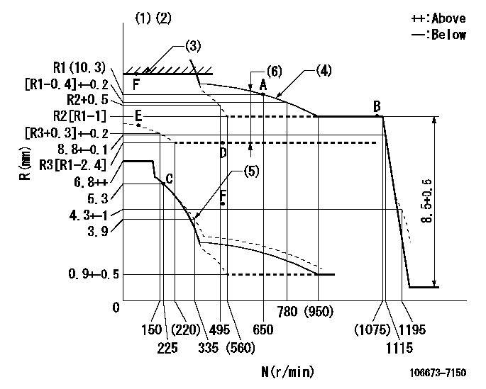
N:Pump speed
R:Rack position (mm)
(1)Tolerance for racks not indicated: +-0.05mm.
(2)RACK LIMIT
(3)Boost compensator cancel stroke: BSL
(4)The torque control spring must does not have a set force.
(5)Damper spring setting
(6)Boost compensator stroke: BCL (N = N1)
----------
BSL=3.8mm BCL=(2.5)mm N1=600r/min
----------
----------
BSL=3.8mm BCL=(2.5)mm N1=600r/min
----------
Speed control lever angle

F:Full speed
----------
----------
a=17deg+-5deg
----------
----------
a=17deg+-5deg
0000000901
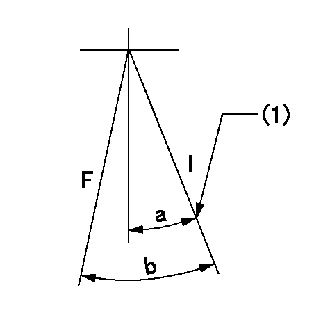
F:Full load
I:Idle
(1)Stopper bolt setting
----------
----------
a=28deg+-5deg b=31deg+-3deg
----------
----------
a=28deg+-5deg b=31deg+-3deg
Stop lever angle

N:Engine manufacturer's normal use
S:Stop the pump.
(1)Rack position = aa
(2)Stopper bolt setting
(3)Rack position bb
(4)Free (at delivery)
----------
aa=3-0.5mm bb=13.3mm
----------
a=28.5deg+-5deg b=(38deg) c=1.5deg+7deg-5deg
----------
aa=3-0.5mm bb=13.3mm
----------
a=28.5deg+-5deg b=(38deg) c=1.5deg+7deg-5deg
0000001501 MICRO SWITCH
Adjustment of the micro-switch
Adjust the bolt to obtain the following lever position when the micro-switch is ON.
(1)Speed N1
(2)Rack position Ra
----------
N1=325r/min Ra=5+-0.1mm
----------
----------
N1=325r/min Ra=5+-0.1mm
----------
Timing setting

(1)Pump vertical direction
(2)Coupling's key groove position at No 1 cylinder's beginning of injection
(3)-
(4)-
----------
----------
a=(7deg)
----------
----------
a=(7deg)
Information:
Do not put oil on the bearings until the bearing clearance has been checked.1. Install bearings (1) in the connecting rods they were removed from. Make sure the tab in each bearing is in alignment with the notch in each connecting rod.2. Install bearings (2) in the cylinder block. Make sure the tab in each bearing is in alignment with the notch in the cylinder block. 3. Install pin (3) in the end of the crankshaft. Install the pin so that it extends a maximum of 6.4 mm (.252 in) above the surface. 4. Install the dowel in the crankshaft that puts gear (4) in the correct position. Install the dowel so that it extends 4.1 0.5 mm (.161 .020 in) above the surface of the crankshaft.5. Heat gear (4) to a maximum temperature of 233° C (451° F). Gear (4) must be installed on the crankshaft with the "V" timing mark toward the outside.6. Install gear (4) on the crankshaft. Make sure the notch in the gear is in alignment with the dowel on the crankshaft. The dimension from the rear face of the gear to the front face of the crankshaft must be 45.54 0.25 mm (1.793 .010 in). 7. Fasten Tooling (A) and a hoist to the crankshaft (5) as shown. Install the crankshaft in the engine. The weight of the crankshaft is approximately 131 kg (290 lb). 8. Make sure that "V" mark (6) on the crankshaft is in alignment with "V" mark (7) on the idler gear. The side of each thrust plate (8) with the words "BLOCK SIDE" must be installed with this side toward the cylinder block.9. Put clean oil on thrust plates (8). Install thrust plates (8) next to the center main bearings. Do not put oil on bearings (9) until the bearing clearances have been checked.10. Put bearings (9) in their original position in crankshaft main bearing caps (10).11. Check the crankshaft main bearing clearance with Plastigage as follows:a. Put a piece of Plastigage between the crankshaft bearing journal surface and bearing (9).b. Install the crankshaft main bearing caps (10) with the arrow on each cap toward the front of cylinder block. Each crankshaft main bearing cap has a number on the bottom surface and must be installed in the same position as the correct number on the left side of the cylinder block.c. Put 2P-2506 Thread Lubricant on the threads of the cap bolts. Install the cap bolts finger tight.d. Tighten the bolts on the tab end of the caps first to a torque of 258 14 N m (190 10 lb ft).e. Tighten the bolts on the other end of the caps to a torque of 258 14 N m (190 10 lb ft).
Do not use an impact wrench to tighten the bolts the additional 120 degrees.
f. Put a mark across the bolt head and cap. Tighten the bolts opposite the tab end of the cap
Do not use an impact wrench to tighten the bolts the additional 120 degrees.
f. Put a mark across the bolt head and cap. Tighten the bolts opposite the tab end of the cap
Have questions with 106673-7150?
Group cross 106673-7150 ZEXEL
Mitsubishi
Mitsubishi
Mitsubishi
106673-7150
9 400 617 329
ME151542
INJECTION-PUMP ASSEMBLY
6D22T3
6D22T3