Information injection-pump assembly
BOSCH
9 400 617 325
9400617325
ZEXEL
106673-7110
1066737110
MITSUBISHI
ME151383
me151383
Rating:
Cross reference number
BOSCH
9 400 617 325
9400617325
ZEXEL
106673-7110
1066737110
MITSUBISHI
ME151383
me151383
Zexel num
Bosch num
Firm num
Name
106673-7110
9 400 617 325
ME151383 MITSUBISHI
INJECTION-PUMP ASSEMBLY
6D22T3 K 14CA INJECTION PUMP ASSY PE6P,6PD PE
6D22T3 K 14CA INJECTION PUMP ASSY PE6P,6PD PE
Calibration Data:
Adjustment conditions
Test oil
1404 Test oil ISO4113 or {SAEJ967d}
1404 Test oil ISO4113 or {SAEJ967d}
Test oil temperature
degC
40
40
45
Nozzle and nozzle holder
105780-8140
Bosch type code
EF8511/9A
Nozzle
105780-0000
Bosch type code
DN12SD12T
Nozzle holder
105780-2080
Bosch type code
EF8511/9
Opening pressure
MPa
17.2
Opening pressure
kgf/cm2
175
Injection pipe
Outer diameter - inner diameter - length (mm) mm 8-3-600
Outer diameter - inner diameter - length (mm) mm 8-3-600
Overflow valve
131424-8020
Overflow valve opening pressure
kPa
255
221
289
Overflow valve opening pressure
kgf/cm2
2.6
2.25
2.95
Tester oil delivery pressure
kPa
157
157
157
Tester oil delivery pressure
kgf/cm2
1.6
1.6
1.6
Direction of rotation (viewed from drive side)
Right R
Right R
Injection timing adjustment
Direction of rotation (viewed from drive side)
Right R
Right R
Injection order
1-5-3-6-
2-4
Pre-stroke
mm
3.9
3.85
3.95
Beginning of injection position
Governor side NO.1
Governor side NO.1
Difference between angles 1
Cal 1-5 deg. 60 59.5 60.5
Cal 1-5 deg. 60 59.5 60.5
Difference between angles 2
Cal 1-3 deg. 120 119.5 120.5
Cal 1-3 deg. 120 119.5 120.5
Difference between angles 3
Cal 1-6 deg. 180 179.5 180.5
Cal 1-6 deg. 180 179.5 180.5
Difference between angles 4
Cyl.1-2 deg. 240 239.5 240.5
Cyl.1-2 deg. 240 239.5 240.5
Difference between angles 5
Cal 1-4 deg. 300 299.5 300.5
Cal 1-4 deg. 300 299.5 300.5
Injection quantity adjustment
Adjusting point
-
Rack position
10
Pump speed
r/min
600
600
600
Each cylinder's injection qty
mm3/st.
169.5
165.3
173.7
Basic
*
Fixing the rack
*
Standard for adjustment of the maximum variation between cylinders
*
Injection quantity adjustment_02
Adjusting point
Z
Rack position
4.3+-0.5
Pump speed
r/min
440
440
440
Each cylinder's injection qty
mm3/st.
20.5
18
23
Fixing the rack
*
Standard for adjustment of the maximum variation between cylinders
*
Injection quantity adjustment_03
Adjusting point
A
Rack position
R1(10)
Pump speed
r/min
600
600
600
Average injection quantity
mm3/st.
169.5
167.5
171.5
Basic
*
Fixing the lever
*
Boost pressure
kPa
93.3
93.3
Boost pressure
mmHg
700
700
Injection quantity adjustment_04
Adjusting point
B
Rack position
R1+0.75
Pump speed
r/min
1100
1100
1100
Average injection quantity
mm3/st.
146.5
138.3
154.7
Fixing the lever
*
Boost pressure
kPa
93.3
93.3
Boost pressure
mmHg
700
700
Injection quantity adjustment_05
Adjusting point
E
Rack position
R1-2.6
Pump speed
r/min
500
500
500
Average injection quantity
mm3/st.
112.5
108.7
116.3
Fixing the lever
*
Boost pressure
kPa
0
0
0
Boost pressure
mmHg
0
0
0
Injection quantity adjustment_06
Adjusting point
F
Rack position
-
Pump speed
r/min
100
100
100
Average injection quantity
mm3/st.
60
40
80
Fixing the lever
*
Boost pressure
kPa
0
0
0
Boost pressure
mmHg
0
0
0
Boost compensator adjustment
Pump speed
r/min
600
600
600
Rack position
R1-2.6
Boost pressure
kPa
3.3
3.3
5.3
Boost pressure
mmHg
25
25
40
Boost compensator adjustment_02
Pump speed
r/min
600
600
600
Rack position
R1-1.55
Boost pressure
kPa
23.3
22
24.6
Boost pressure
mmHg
175
165
185
Boost compensator adjustment_03
Pump speed
r/min
600
600
600
Rack position
R1(10)
Boost pressure
kPa
80
80
80
Boost pressure
mmHg
600
600
600
Timer adjustment
Pump speed
r/min
900--
Advance angle
deg.
0
0
0
Remarks
Start
Start
Timer adjustment_02
Pump speed
r/min
850
Advance angle
deg.
0.5
Timer adjustment_03
Pump speed
r/min
1100
Advance angle
deg.
1.5
1
2
Remarks
Finish
Finish
Test data Ex:
Governor adjustment
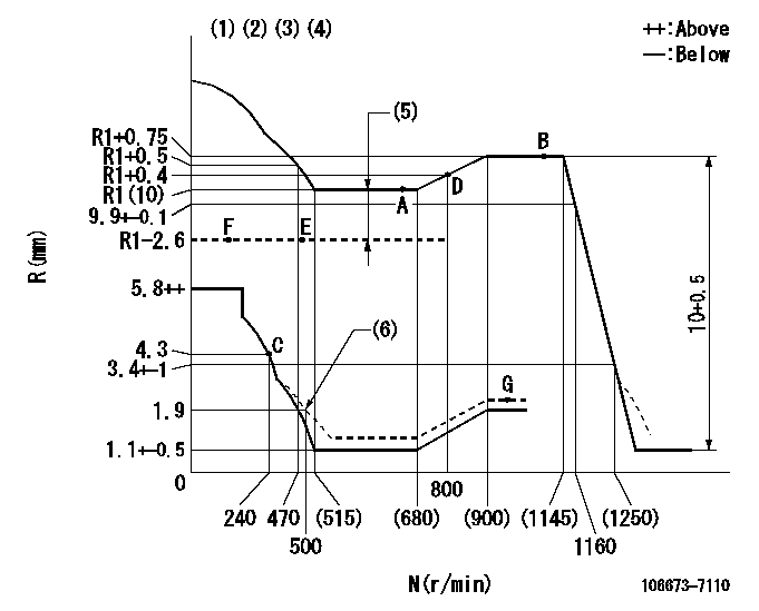
N:Pump speed
R:Rack position (mm)
(1)Lever ratio: RT
(2)Target shim dimension: TH
(3)Tolerance for racks not indicated: +-0.05mm.
(4)Boost compensator cancel stroke: BSL
(5)Boost compensator stroke: BCL
(6)Damper spring setting
----------
RT=1 TH=2.1mm BSL=4mm BCL=2.6+-0.1mm
----------
----------
RT=1 TH=2.1mm BSL=4mm BCL=2.6+-0.1mm
----------
Speed control lever angle

F:Full speed
----------
----------
a=17deg+-5deg
----------
----------
a=17deg+-5deg
0000000901
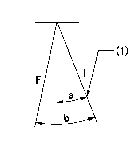
F:Full load
I:Idle
(1)Stopper bolt setting
----------
----------
a=28deg+-5deg b=32deg+-3deg
----------
----------
a=28deg+-5deg b=32deg+-3deg
Stop lever angle
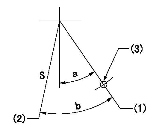
S:Stop the pump.
(1)Free (at delivery)
(2)Rack position = aa (non-injection rack position). Set the stopper bolt at speed = bb.
(3)Use the hole above R = cc
----------
aa=2.9-0.5mm bb=240r/min cc=37mm
----------
a=38deg+-5deg b=40deg+7deg-5deg
----------
aa=2.9-0.5mm bb=240r/min cc=37mm
----------
a=38deg+-5deg b=40deg+7deg-5deg
0000001501 MICRO SWITCH
Adjustment of the micro-switch
Adjust the bolt to obtain the following lever position when the micro-switch is ON.
(1)Speed N1
(2)Rack position Ra
----------
N1=325r/min Ra=4.3+-0.1mm
----------
----------
N1=325r/min Ra=4.3+-0.1mm
----------
Timing setting

(1)Pump vertical direction
(2)Coupling's key groove position at No 1 cylinder's beginning of injection
(3)B.T.D.C.: aa
(4)-
----------
aa=9deg
----------
a=(3deg)
----------
aa=9deg
----------
a=(3deg)
Information:
Start By:a. remove timing gear coverb. remove push rods and valve lifters 1. Remove air compressor outlet hose (1). (Not applicable).2. Remove air compressor air inlet tube (3). (Not applicable).3. Remove air compressor coolant outlet tube (4). (Not applicable)4. Remove turbocharger oil return tube (2). 5. Use Tooling (A) to remove studs (5).6. Turn the flywheel with Tool (B), and remove each bolt (6) as it becomes accessible.7. Turn the flywheel with Tool (B) until the "V" marks on the front timing gears are in alignment.8. Install Tooling (C) through the holes for studs (5) into camshaft rear gear (7).
Tooling (C) must be used to prevent the loss of rear balance weight timing and to keep the camshaft rear gear in place when the camshaft is removed.
9. Tighten Tooling (C) evenly to remove the camshaft rear gear from the camshaft. 10. Remove thrust plate (8).
Be careful not to damage the camshaft bearings. Do not pry the camshaft out of the cylinder block. If resistance to camshaft removal occurs, turn the camshaft so the lobes will align the bearing journals with the camshaft bearing bores.
11. Carefully remove the camshaft and gear (9) from the cylinder block.12. If removal of the camshaft gear is necessary, place the camshaft and gear in a hydraulic press. Place Tool (D) over the camshaft, and press against it to remove the camshaft from the gear.
Be careful not to scratch or mar the finished surfaces of the camshaft.
13. Remove the key from the camshaft.14. If dowel removal is necessary, use Tool (E) to remove the dowel.Install Camshaft
1. Install the key in the camshaft. Be sure the key is seated in the camshaft.2. Install the pin in the rear of the camshaft. Install the pin to a height of 8.51 to 9.01 mm (.335 to .355 in).3. Heat the camshaft drive gear to a maximum temperature of 204° C (400° F), align the groove in the drive gear with the key in the camshaft, and install the camshaft drive gear with the timing marks away from the camshaft.4. Put clean engine oil on the camshaft bearing journals and lobes.5. Carefully install the camshaft into the cylinder block. Do not force the camshaft into position. If resistance to camshaft installation occurs, turn the camshaft so the lobes will align the bearing journals with the camshaft bearing bores. 6. Align the "V" marks on camshaft drive gear (2) and idler gear (3).7. Install thrust plate (1) to hold the camshaft and camshaft drive gear (2) in the cylinder block. 8. Loosen the bolts Tool (B) that hold camshaft rear gear (5) so camshaft rear gear (5) will engage the dowel on the rear of the camshaft.9. After the dowel is engaged, remove Tool (B), and install bolts (4).10. Use Tool (A) to turn the flywheel, and install each of four bolts (4). Tighten bolts (4) to a torque of 23 to 31 N m (17 to 23 lb ft).11. Put 5P-3413 Pipe Sealant with "Teflon" on the
Have questions with 106673-7110?
Group cross 106673-7110 ZEXEL
Mitsubishi
106673-7110
9 400 617 325
ME151383
INJECTION-PUMP ASSEMBLY
6D22T3
6D22T3