Information injection-pump assembly
BOSCH
9 400 610 920
9400610920
ZEXEL
106673-7041
1066737041
MITSUBISHI
ME158001
me158001
Rating:
Service parts 106673-7041 INJECTION-PUMP ASSEMBLY:
1.
_
7.
COUPLING PLATE
8.
_
9.
_
11.
Nozzle and Holder
ME059621
12.
Open Pre:MPa(Kqf/cm2)
21.6{220}

15.
NOZZLE SET
Include in #1:
106673-7041
as INJECTION-PUMP ASSEMBLY
Cross reference number
BOSCH
9 400 610 920
9400610920
ZEXEL
106673-7041
1066737041
MITSUBISHI
ME158001
me158001
Zexel num
Bosch num
Firm num
Name
106673-7041
9 400 610 920
ME158001 MITSUBISHI
INJECTION-PUMP ASSEMBLY
6D22T * K
6D22T * K
Calibration Data:
Adjustment conditions
Test oil
1404 Test oil ISO4113 or {SAEJ967d}
1404 Test oil ISO4113 or {SAEJ967d}
Test oil temperature
degC
40
40
45
Nozzle and nozzle holder
105780-8140
Bosch type code
EF8511/9A
Nozzle
105780-0000
Bosch type code
DN12SD12T
Nozzle holder
105780-2080
Bosch type code
EF8511/9
Opening pressure
MPa
17.2
Opening pressure
kgf/cm2
175
Injection pipe
Outer diameter - inner diameter - length (mm) mm 8-3-600
Outer diameter - inner diameter - length (mm) mm 8-3-600
Overflow valve
131424-4620
Overflow valve opening pressure
kPa
255
221
289
Overflow valve opening pressure
kgf/cm2
2.6
2.25
2.95
Tester oil delivery pressure
kPa
157
157
157
Tester oil delivery pressure
kgf/cm2
1.6
1.6
1.6
Direction of rotation (viewed from drive side)
Right R
Right R
Injection timing adjustment
Direction of rotation (viewed from drive side)
Right R
Right R
Injection order
1-5-3-6-
2-4
Pre-stroke
mm
4.8
4.75
4.85
Beginning of injection position
Governor side NO.1
Governor side NO.1
Difference between angles 1
Cal 1-5 deg. 60 59.5 60.5
Cal 1-5 deg. 60 59.5 60.5
Difference between angles 2
Cal 1-3 deg. 120 119.5 120.5
Cal 1-3 deg. 120 119.5 120.5
Difference between angles 3
Cal 1-6 deg. 180 179.5 180.5
Cal 1-6 deg. 180 179.5 180.5
Difference between angles 4
Cyl.1-2 deg. 240 239.5 240.5
Cyl.1-2 deg. 240 239.5 240.5
Difference between angles 5
Cal 1-4 deg. 300 299.5 300.5
Cal 1-4 deg. 300 299.5 300.5
Injection quantity adjustment
Adjusting point
A
Rack position
11.7
Pump speed
r/min
1100
1100
1100
Average injection quantity
mm3/st.
138.5
135.5
141.5
Max. variation between cylinders
%
0
-3
3
Basic
*
Fixing the lever
*
Injection quantity adjustment_02
Adjusting point
B
Rack position
5.8+-0.5
Pump speed
r/min
315
315
315
Average injection quantity
mm3/st.
12
9.4
14.6
Max. variation between cylinders
%
0
-15
15
Fixing the rack
*
Injection quantity adjustment_03
Adjusting point
D
Rack position
-
Pump speed
r/min
100
100
100
Average injection quantity
mm3/st.
150
130
170
Fixing the lever
*
Rack limit
*
Timer adjustment
Pump speed
r/min
1100++
Advance angle
deg.
0
0
0
Remarks
Do not advance until starting N = 1100.
Do not advance until starting N = 1100.
Timer adjustment_02
Pump speed
r/min
1100
Advance angle
deg.
0.5
Timer adjustment_03
Pump speed
r/min
-
Advance angle
deg.
2
2
2
Remarks
Measure the actual speed, stop
Measure the actual speed, stop
Test data Ex:
Governor adjustment
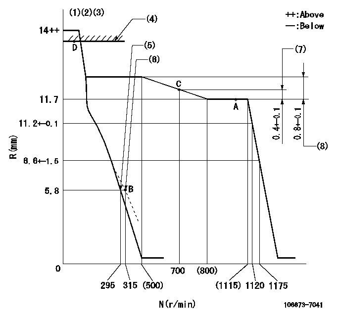
N:Pump speed
R:Rack position (mm)
(1)Notch fixed: K
(2)Tolerance for racks not indicated: +-0.05mm.
(3)Torque spring does not operate.
(4)RACK LIMIT
(5)Main spring setting
(6)Set idle sub-spring
(7)Rack difference between N = N1 and N = N2
(8)Rack difference between N = N3 and N = N4
----------
K=8 N1=1100r/min N2=700r/min N3=1100r/min N4=450r/min
----------
----------
K=8 N1=1100r/min N2=700r/min N3=1100r/min N4=450r/min
----------
Speed control lever angle

F:Full speed
I:Idle
(1)Stopper bolt setting
----------
----------
a=31deg+-5deg b=12deg+-5deg
----------
----------
a=31deg+-5deg b=12deg+-5deg
Stop lever angle
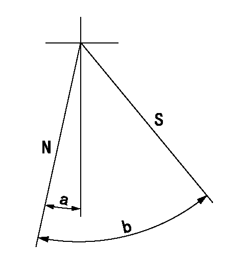
N:Pump normal
S:Stop the pump.
----------
----------
a=19deg+-5deg b=53deg+-5deg
----------
----------
a=19deg+-5deg b=53deg+-5deg
Timing setting

(1)Pump vertical direction
(2)Coupling's key groove position at No 1 cylinder's beginning of injection
(3)-
(4)-
----------
----------
a=(7deg)
----------
----------
a=(7deg)
Information:
9. Remove bracket assembly (16) and link (17). 10. Put identification marks on fuel racks (18) and (19), and remove the fuel racks. 11. Put identification marks on each spacer (20) and lifter (21) so they can be installed in their original position. 12. Remove fuel injection pump camshaft (22) from the pump housing.13. Remove O-ring seal (23). 14. Inspect link pivot shaft (24) and bracket locating pin (25). Make a replacement by removal of shaft (24) and dowel (25) with Tool (D). 15. Inspect upper bearing (26) and the lower bearing that hold the pinion gear in the pump housing.16. Make a replacement of bearings (26) if necessary.17. Inspect idler gear shaft (27). If a replacement is necessary, remove the shaft with Tooling (D). 18. Inspect fuel rack bearings (28) and camshaft bearings (29). If a replacement is necessary, remove bearings (28) and (29).19. Use Tooling (E) to remove bearings (28). 20. Remove regulator valve (30). 21. Remove pin (31) to disassemble the regulator valve, and inspect the components.22. Piston (32) must move freely in valve body (30).23. Make a reference to the Specifications for spring (34).24. Make a replacement of O-ring seals (33).Assemble Fuel Injection Pump Housing
Pin (2) must not extend out of either side of valve body (3).
1. Install spring (4), piston (1) and pin (2) in valve body (3).2. Put clean engine oil on the valve body and O-ring seals (5). Install the oil bypass valve in the pump housing. Tighten the bypass valve body to a torque of 68 14 N m (50 10 lb ft). 3. Install the camshaft front and rear bearings with Tooling (A). Install the front bearing until it is a distance of 1.0 0.5 mm (.04 .02 in) from the front surface of the pump housing. Make sure both oil holes in bearing are in alignment with the oil holes in the pump housing. 4. Put Tool (B) in the fuel pump housing with the dowels of Tool (B) in alignment with the left fuel rack bore. Install the bolt that holds the tool in place on the housing.5. Put a new bearing in position with the tab of the bearing up. Install the bearing with Tool (C) until the shoulder of Tool (C) makes contact with Tool (B).6. Turn Tool (B), and make an alignment of the dowels on Tool (B) with the right fuel rack bore.7. Do Step 3 again for the left fuel rack bearing. 8. Install shaft (6) to a height of 16.8 0.5 mm (.66 .02 in). 9. Make sure the chamfer on the lower bearing for the pinion gear is toward the inside and the notch is in the location shown. Install the bearing 28.4 0.5 mm (1.12 .02 in) below the bearing bore surface with Tooling (D).10. Make sure the chamfer on the upper bearing for the pinion gear is toward the inside and the notch is in the location shown. Use
Have questions with 106673-7041?
Group cross 106673-7041 ZEXEL
Mitsubishi
Mitsubishi
Mitsubishi
Mitsubishi
106673-7041
9 400 610 920
ME158001
INJECTION-PUMP ASSEMBLY
6D22T
6D22T