Information injection-pump assembly
BOSCH
9 400 617 318
9400617318
ZEXEL
106673-5060
1066735060
NISSAN-DIESEL
16790NB007
16790nb007
Rating:
Service parts 106673-5060 INJECTION-PUMP ASSEMBLY:
1.
_
7.
COUPLING PLATE
8.
_
9.
_
11.
Nozzle and Holder
16600NB002
12.
Open Pre:MPa(Kqf/cm2)
22.6{230}
15.
NOZZLE SET
Include in #1:
106673-5060
as INJECTION-PUMP ASSEMBLY
Cross reference number
BOSCH
9 400 617 318
9400617318
ZEXEL
106673-5060
1066735060
NISSAN-DIESEL
16790NB007
16790nb007
Zexel num
Bosch num
Firm num
Name
106673-5060
9 400 617 318
16790NB007 NISSAN-DIESEL
INJECTION-PUMP ASSEMBLY
PF6TA K 14CA INJECTION PUMP ASSY PE6P,6PD PE
PF6TA K 14CA INJECTION PUMP ASSY PE6P,6PD PE
Calibration Data:
Adjustment conditions
Test oil
1404 Test oil ISO4113 or {SAEJ967d}
1404 Test oil ISO4113 or {SAEJ967d}
Test oil temperature
degC
40
40
45
Nozzle and nozzle holder
105780-8140
Bosch type code
EF8511/9A
Nozzle
105780-0000
Bosch type code
DN12SD12T
Nozzle holder
105780-2080
Bosch type code
EF8511/9
Opening pressure
MPa
17.2
Opening pressure
kgf/cm2
175
Injection pipe
Outer diameter - inner diameter - length (mm) mm 8-3-600
Outer diameter - inner diameter - length (mm) mm 8-3-600
Overflow valve
134424-4120
Overflow valve opening pressure
kPa
255
221
289
Overflow valve opening pressure
kgf/cm2
2.6
2.25
2.95
Tester oil delivery pressure
kPa
255
255
255
Tester oil delivery pressure
kgf/cm2
2.6
2.6
2.6
Direction of rotation (viewed from drive side)
Right R
Right R
Injection timing adjustment
Direction of rotation (viewed from drive side)
Right R
Right R
Injection order
1-4-2-6-
3-5
Pre-stroke
mm
4.2
4.15
4.25
Beginning of injection position
Drive side NO.1
Drive side NO.1
Difference between angles 1
Cal 1-4 deg. 60 59.5 60.5
Cal 1-4 deg. 60 59.5 60.5
Difference between angles 2
Cyl.1-2 deg. 120 119.5 120.5
Cyl.1-2 deg. 120 119.5 120.5
Difference between angles 3
Cal 1-6 deg. 180 179.5 180.5
Cal 1-6 deg. 180 179.5 180.5
Difference between angles 4
Cal 1-3 deg. 240 239.5 240.5
Cal 1-3 deg. 240 239.5 240.5
Difference between angles 5
Cal 1-5 deg. 300 299.5 300.5
Cal 1-5 deg. 300 299.5 300.5
Injection quantity adjustment
Adjusting point
A
Rack position
14.3
Pump speed
r/min
700
700
700
Average injection quantity
mm3/st.
238
236
240
Max. variation between cylinders
%
0
-4
4
Basic
*
Fixing the lever
*
Boost pressure
kPa
140
140
Boost pressure
mmHg
1050
1050
Injection quantity adjustment_02
Adjusting point
C
Rack position
8+-0.5
Pump speed
r/min
375
375
375
Average injection quantity
mm3/st.
13.5
12.5
14.5
Max. variation between cylinders
%
0
-10
10
Fixing the rack
*
Boost pressure
kPa
0
0
0
Boost pressure
mmHg
0
0
0
Boost compensator adjustment
Pump speed
r/min
500
500
500
Rack position
R1-3.5
Boost pressure
kPa
16
13.3
18.7
Boost pressure
mmHg
120
100
140
Boost compensator adjustment_02
Pump speed
r/min
500
500
500
Rack position
R1(14.3)
Boost pressure
kPa
127
127
127
Boost pressure
mmHg
950
950
950
Timer adjustment
Pump speed
r/min
700-50
Advance angle
deg.
0.3
Timer adjustment_02
Pump speed
r/min
-
Advance angle
deg.
1
0.5
1.5
Remarks
Measure the actual speed.
Measure the actual speed.
Timer adjustment_03
Pump speed
r/min
-
Advance angle
deg.
2
2
2
Remarks
Measure the actual speed, stop
Measure the actual speed, stop
Test data Ex:
Governor adjustment
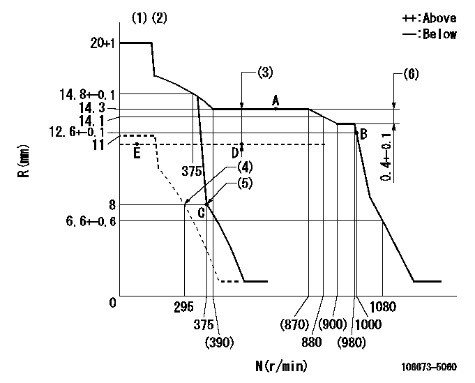
N:Pump speed
R:Rack position (mm)
(1)Target notch: K
(2)Tolerance for racks not indicated: +-0.05mm.
(3)Boost compensator stroke: BCL
(4)Set idle sub-spring
(5)Main spring setting
(6)Rack difference between N = N1 and N = N2
----------
K=14 BCL=3.5+-0.1mm N1=950r/min N2=700r/min
----------
----------
K=14 BCL=3.5+-0.1mm N1=950r/min N2=700r/min
----------
Speed control lever angle

F:Full speed
I:Idle
(1)Use the hole at R = aa
(2)Stopper bolt setting
----------
aa=100mm
----------
a=11deg+-5deg b=24deg+-5deg
----------
aa=100mm
----------
a=11deg+-5deg b=24deg+-5deg
Stop lever angle
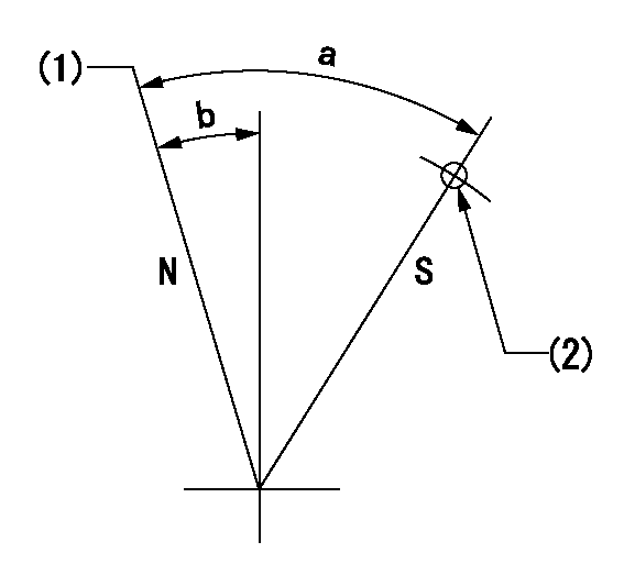
N:Pump normal
S:Stop the pump.
(1)Normal
(2)Use the hole at R = aa
----------
aa=55mm
----------
a=53deg+-5deg b=26.5deg+-5deg
----------
aa=55mm
----------
a=53deg+-5deg b=26.5deg+-5deg
Timing setting

(1)Pump vertical direction
(2)Coupling's key groove position at No 1 cylinder's beginning of injection
(3)-
(4)-
----------
----------
a=(30deg)
----------
----------
a=(30deg)
Information:
Typical Example1. Turn the crankshaft until the "C" mark on the crankshaft gear is in alignment with the "C" mark on the camshaft gear. To keep the engine timing correct during removal and installation of the camshaft, put a mark on the teeth of the fuel injection pump drive gear and idler gear at location (A). Put a mark on the teeth of the idler gear and camshaft gear at location (B). When installing the camshaft, the engine timing will be correct when the marks at locations (A) and (B) are in alignment and the "C" marks on the crankshaft and camshaft gears are in alignment.2. Remove the bolts, lock and washer (1) that hold the camshaft in position.3. Remove the camshaft and gear (2). Do not cause damage to the lobes or bearings when the camshaft is removed.4. If necessary, remove the bolts and gear from the camshaft. The following steps are for the installation of the camshaft.5. Put the camshaft drive gear in position on the end of the camshaft, and install the bolts that hold it. Tighten the bolts to a torque of 55 7 N m (41 5 lb ft).
Do not cause damage to the lobes or bearings when the camshaft is installed.
6. Put 2P2506 Thread Lubricant on the camshaft lobes only, and clean engine oil on the bearing journals. Install camshaft (3) in the cylinder block, and make an alignment of the "C" marks and the marks put on the gears during removal.7. Install washer (1), the lock and bolts to hold the camshaft in position.End By:a. install valve liftersb. install timing gear cover
Have questions with 106673-5060?
Group cross 106673-5060 ZEXEL
Nissan-Diesel
Nissan-Diesel
106673-5060
9 400 617 318
16790NB007
INJECTION-PUMP ASSEMBLY
PF6TA
PF6TA