Information injection-pump assembly
BOSCH
9 400 613 510
9400613510
ZEXEL
106673-5041
1066735041
NISSAN-DIESEL
16790NB005
16790nb005
Rating:
Service parts 106673-5041 INJECTION-PUMP ASSEMBLY:
1.
_
7.
COUPLING PLATE
8.
_
9.
_
11.
Nozzle and Holder
16600NB001
12.
Open Pre:MPa(Kqf/cm2)
22.6{230}
15.
NOZZLE SET
Include in #1:
106673-5041
as INJECTION-PUMP ASSEMBLY
Cross reference number
BOSCH
9 400 613 510
9400613510
ZEXEL
106673-5041
1066735041
NISSAN-DIESEL
16790NB005
16790nb005
Zexel num
Bosch num
Firm num
Name
106673-5041
9 400 613 510
16790NB005 NISSAN-DIESEL
INJECTION-PUMP ASSEMBLY
PF6TA K 14CA INJECTION PUMP ASSY PE6P,6PD PE
PF6TA K 14CA INJECTION PUMP ASSY PE6P,6PD PE
Calibration Data:
Adjustment conditions
Test oil
1404 Test oil ISO4113 or {SAEJ967d}
1404 Test oil ISO4113 or {SAEJ967d}
Test oil temperature
degC
40
40
45
Nozzle and nozzle holder
105780-8140
Bosch type code
EF8511/9A
Nozzle
105780-0000
Bosch type code
DN12SD12T
Nozzle holder
105780-2080
Bosch type code
EF8511/9
Opening pressure
MPa
17.2
Opening pressure
kgf/cm2
175
Injection pipe
Outer diameter - inner diameter - length (mm) mm 8-3-600
Outer diameter - inner diameter - length (mm) mm 8-3-600
Overflow valve
134424-4120
Overflow valve opening pressure
kPa
255
221
289
Overflow valve opening pressure
kgf/cm2
2.6
2.25
2.95
Tester oil delivery pressure
kPa
255
255
255
Tester oil delivery pressure
kgf/cm2
2.6
2.6
2.6
Direction of rotation (viewed from drive side)
Right R
Right R
Injection timing adjustment
Direction of rotation (viewed from drive side)
Right R
Right R
Injection order
1-4-2-6-
3-5
Pre-stroke
mm
4.2
4.15
4.25
Beginning of injection position
Drive side NO.1
Drive side NO.1
Difference between angles 1
Cal 1-4 deg. 60 59.5 60.5
Cal 1-4 deg. 60 59.5 60.5
Difference between angles 2
Cyl.1-2 deg. 120 119.5 120.5
Cyl.1-2 deg. 120 119.5 120.5
Difference between angles 3
Cal 1-6 deg. 180 179.5 180.5
Cal 1-6 deg. 180 179.5 180.5
Difference between angles 4
Cal 1-3 deg. 240 239.5 240.5
Cal 1-3 deg. 240 239.5 240.5
Difference between angles 5
Cal 1-5 deg. 300 299.5 300.5
Cal 1-5 deg. 300 299.5 300.5
Injection quantity adjustment
Adjusting point
A
Rack position
13.5
Pump speed
r/min
700
700
700
Average injection quantity
mm3/st.
212
210
214
Max. variation between cylinders
%
0
-4
4
Basic
*
Fixing the lever
*
Boost pressure
kPa
128
128
Boost pressure
mmHg
960
960
Injection quantity adjustment_02
Adjusting point
C
Rack position
7.8+-0.5
Pump speed
r/min
375
375
375
Average injection quantity
mm3/st.
12
11
13
Max. variation between cylinders
%
0
-10
10
Fixing the rack
*
Boost pressure
kPa
0
0
0
Boost pressure
mmHg
0
0
0
Boost compensator adjustment
Pump speed
r/min
500
500
500
Rack position
R1-3.15
Boost pressure
kPa
16
13.3
18.7
Boost pressure
mmHg
120
100
140
Boost compensator adjustment_02
Pump speed
r/min
500
500
500
Rack position
R1(13.5)
Boost pressure
kPa
115
115
115
Boost pressure
mmHg
860
860
860
Timer adjustment
Pump speed
r/min
700-50
Advance angle
deg.
0.3
Timer adjustment_02
Pump speed
r/min
-
Advance angle
deg.
1
0.5
1.5
Remarks
Measure the actual speed.
Measure the actual speed.
Timer adjustment_03
Pump speed
r/min
-
Advance angle
deg.
2
2
2
Remarks
Measure the actual speed, stop
Measure the actual speed, stop
Test data Ex:
Governor adjustment
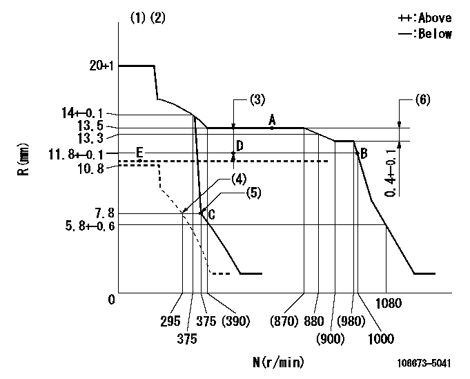
N:Pump speed
R:Rack position (mm)
(1)Target notch: K
(2)Tolerance for racks not indicated: +-0.05mm.
(3)Boost compensator stroke: BCL
(4)Set idle sub-spring
(5)Main spring setting
(6)Rack difference between N = N1 and N = N2
----------
K=14 BCL=3.15+-0.1mm N1=950r/min N2=700r/min
----------
----------
K=14 BCL=3.15+-0.1mm N1=950r/min N2=700r/min
----------
Speed control lever angle

F:Full speed
I:Idle
(1)Use the hole at R = aa
(2)Stopper bolt setting
----------
aa=100mm
----------
a=9deg+-5deg b=24deg+-5deg
----------
aa=100mm
----------
a=9deg+-5deg b=24deg+-5deg
Stop lever angle
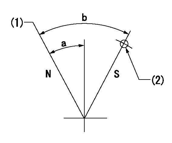
N:Pump normal
S:Stop the pump.
(1)Normal
(2)Use the hole at R = aa
----------
aa=55mm
----------
a=26.5deg+-5deg b=53deg+-5deg
----------
aa=55mm
----------
a=26.5deg+-5deg b=53deg+-5deg
Timing setting

(1)Pump vertical direction
(2)Coupling's key groove position at No 1 cylinder's beginning of injection
(3)-
(4)-
----------
----------
a=(30deg)
----------
----------
a=(30deg)
Information:
2. Remove covers (1) and (2) from the back side of the timing gear plate. 3. Remove the two bolts and clamp from location (X) that hold the crankshaft front seal adapter in position. Remove the crankshaft front seal adapter and front seal from the engine as a unit.4. Remove all bolts (3) that hold the timing gear cover in position on the engine. Remove timing gear cover (4) and the gasket from the engine.Install Timing Gear Cover
1. Put the gasket and timing gear cover (1) in position on the engine, and install the bolts that hold it. Tighten the two bolts at location (X) to a torque of 23 4 N m (17 3 lb ft).2. Put the crankshaft front seal adapter and seal in position in the timing gear cover. Install the clamp that holds it. 3. Put the gasket, cover (2) and clamp (3) in position. Install the bolts that hold them. Install the O-ring seal, cover (4) and the bolts that hold them.4. Trim the timing gear cover gasket so it is even with the bottom of the cylinder block.5. Put a thin coat of 3S6252 RTV Silicone Adhesive/Sealant to the bottom surface of the timing gear cover gasket. Remove the shims, and install the oil pan bolts. If it was necessary to remove the oil pan plate, see topic, "Remove & Install Oil Pan Plate". Install the oil pan plate.End By:a. install vibration damper and pulley (3306)b. install crankshaft pulley (3304)c. install gauge group (if equipped)d. install front supporte. install water pump
1. Put the gasket and timing gear cover (1) in position on the engine, and install the bolts that hold it. Tighten the two bolts at location (X) to a torque of 23 4 N m (17 3 lb ft).2. Put the crankshaft front seal adapter and seal in position in the timing gear cover. Install the clamp that holds it. 3. Put the gasket, cover (2) and clamp (3) in position. Install the bolts that hold them. Install the O-ring seal, cover (4) and the bolts that hold them.4. Trim the timing gear cover gasket so it is even with the bottom of the cylinder block.5. Put a thin coat of 3S6252 RTV Silicone Adhesive/Sealant to the bottom surface of the timing gear cover gasket. Remove the shims, and install the oil pan bolts. If it was necessary to remove the oil pan plate, see topic, "Remove & Install Oil Pan Plate". Install the oil pan plate.End By:a. install vibration damper and pulley (3306)b. install crankshaft pulley (3304)c. install gauge group (if equipped)d. install front supporte. install water pump
Have questions with 106673-5041?
Group cross 106673-5041 ZEXEL
Nissan-Diesel
Nissan-Diesel
106673-5041
9 400 613 510
16790NB005
INJECTION-PUMP ASSEMBLY
PF6TA
PF6TA