Information injection-pump assembly
BOSCH
9 400 613 011
9400613011
ZEXEL
106673-4210
1066734210
KOMATSU
6152721510
6152721510
Rating:
Service parts 106673-4210 INJECTION-PUMP ASSEMBLY:
1.
_

7.
COUPLING PLATE
8.
_
9.
_
11.
Nozzle and Holder
6152-12-3300
12.
Open Pre:MPa(Kqf/cm2)
27.5{280}
15.
NOZZLE SET
Include in #1:
106673-4210
as INJECTION-PUMP ASSEMBLY
Cross reference number
BOSCH
9 400 613 011
9400613011
ZEXEL
106673-4210
1066734210
KOMATSU
6152721510
6152721510
Zexel num
Bosch num
Firm num
Name
106673-4210
9 400 613 011
6152721510 KOMATSU
INJECTION-PUMP ASSEMBLY
SA6D125 K 14CA INJECTION PUMP ASSY PE6P,6PD PE
SA6D125 K 14CA INJECTION PUMP ASSY PE6P,6PD PE
Calibration Data:
Adjustment conditions
Test oil
1404 Test oil ISO4113 or {SAEJ967d}
1404 Test oil ISO4113 or {SAEJ967d}
Test oil temperature
degC
40
40
45
Nozzle and nozzle holder
105780-8140
Bosch type code
EF8511/9A
Nozzle
105780-0000
Bosch type code
DN12SD12T
Nozzle holder
105780-2080
Bosch type code
EF8511/9
Opening pressure
MPa
17.2
Opening pressure
kgf/cm2
175
Injection pipe
Outer diameter - inner diameter - length (mm) mm 8-3-600
Outer diameter - inner diameter - length (mm) mm 8-3-600
Overflow valve
131424-1520
Overflow valve opening pressure
kPa
157
157
157
Overflow valve opening pressure
kgf/cm2
1.6
1.6
1.6
Tester oil delivery pressure
kPa
157
157
157
Tester oil delivery pressure
kgf/cm2
1.6
1.6
1.6
Direction of rotation (viewed from drive side)
Left L
Left L
Injection timing adjustment
Direction of rotation (viewed from drive side)
Left L
Left L
Injection order
1-5-3-6-
2-4
Pre-stroke
mm
3.8
3.75
3.85
Beginning of injection position
Drive side NO.1
Drive side NO.1
Difference between angles 1
Cal 1-5 deg. 60 59.5 60.5
Cal 1-5 deg. 60 59.5 60.5
Difference between angles 2
Cal 1-3 deg. 120 119.5 120.5
Cal 1-3 deg. 120 119.5 120.5
Difference between angles 3
Cal 1-6 deg. 180 179.5 180.5
Cal 1-6 deg. 180 179.5 180.5
Difference between angles 4
Cyl.1-2 deg. 240 239.5 240.5
Cyl.1-2 deg. 240 239.5 240.5
Difference between angles 5
Cal 1-4 deg. 300 299.5 300.5
Cal 1-4 deg. 300 299.5 300.5
Injection quantity adjustment
Adjusting point
A
Rack position
9.8
Pump speed
r/min
1050
1050
1050
Average injection quantity
mm3/st.
186
182
190
Max. variation between cylinders
%
0
-3
3
Basic
*
Fixing the lever
*
Boost pressure
kPa
40
40
Boost pressure
mmHg
300
300
Injection quantity adjustment_02
Adjusting point
Z
Rack position
5.8+-0.5
Pump speed
r/min
500
500
500
Average injection quantity
mm3/st.
27
25.5
28.5
Max. variation between cylinders
%
0
-6
6
Fixing the rack
*
Boost pressure
kPa
0
0
0
Boost pressure
mmHg
0
0
0
Boost compensator adjustment
Pump speed
r/min
700
700
700
Rack position
8
Boost pressure
kPa
6.7
5.4
8
Boost pressure
mmHg
50
40
60
Boost compensator adjustment_02
Pump speed
r/min
700
700
700
Rack position
10.5
Boost pressure
kPa
26.7
20
33.4
Boost pressure
mmHg
200
150
250
Timer adjustment
Pump speed
r/min
800--
Advance angle
deg.
0
0
0
Remarks
Start
Start
Timer adjustment_02
Pump speed
r/min
750
Advance angle
deg.
0.5
Timer adjustment_03
Pump speed
r/min
1050
Advance angle
deg.
3
2.5
3.5
Remarks
Finish
Finish
Test data Ex:
Governor adjustment
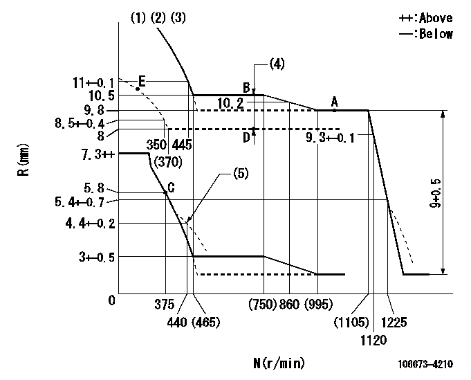
N:Pump speed
R:Rack position (mm)
(1)Lever ratio: RT
(2)Target shim dimension: TH
(3)Tolerance for racks not indicated: +-0.05mm.
(4)Boost compensator stroke: BCL
(5)Damper spring setting
----------
RT=1 TH=2.2mm BCL=(2.5)mm
----------
----------
RT=1 TH=2.2mm BCL=(2.5)mm
----------
Speed control lever angle

F:Full speed
----------
----------
a=19deg+-5deg
----------
----------
a=19deg+-5deg
0000000901
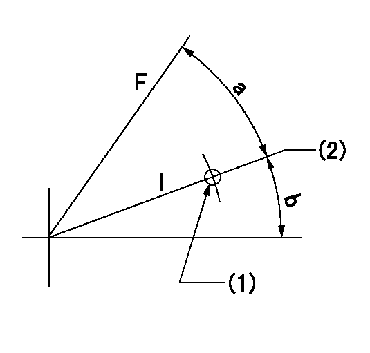
F:Full load
I:Idle
(1)Use the pin at R = aa
(2)Stopper bolt setting
----------
aa=50mm
----------
a=27.5deg+-3deg b=24deg+-5deg
----------
aa=50mm
----------
a=27.5deg+-3deg b=24deg+-5deg
Stop lever angle
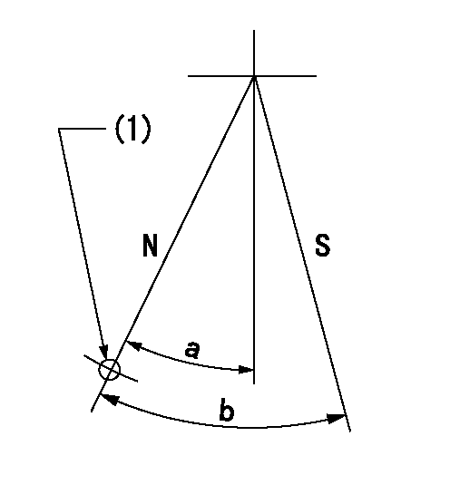
N:Pump normal
S:Stop the pump.
(1)Use the hole at R = aa
----------
aa=26mm
----------
a=37deg+-5deg b=71deg+-5deg
----------
aa=26mm
----------
a=37deg+-5deg b=71deg+-5deg
Timing setting

(1)Pump vertical direction
(2)Coupling's key groove position at No 1 cylinder's beginning of injection
(3)B.T.D.C.: aa
(4)-
----------
aa=12deg
----------
a=(150deg)
----------
aa=12deg
----------
a=(150deg)
Information:
2. Turn the crankshaft until two pistons are at bottom center.3. Remove bolts (1) and the bearing caps. Push the rods and pistons up until the rings are out of the cylinder liners. 4. Remove pistons (2) and connecting rods from the cylinder liners.5. Do Steps 1 through 4 for the remainder of the pistons and connecting rods.Install Pistons & Connecting Rod Assemblies
1. Put clean engine oil on piston rings, connecting rod bearings and cylinder liners. 2. Use Tool (A), and install piston (2) and the connecting rod in the cylinder liner.3. Install the bearing cap on the connecting rod with the number on the side of the bearing cap on the same side and same number as on the connecting rod.4. Put 2P2506 Thread Lubricant on the threads of the bolts. Install the nuts, and tighten them to a torque of 90 8 N m (67 6 lb ft). Put a mark on the nuts and cap, and tighten the nuts an extra 90 5 degrees.5. Do Steps 1 through 4 for the remainder of the pistons and connecting rods.End By:a. install piston cooling tubesb. install oil pumpc. install cylinder head assemblyDisassemble & Assemble Pistons & Connecting Rod Assemblies
Start By:a. remove pistons and connecting rod assemblies 1. Remove bearings (3) from the connecting rod and connecting rod cap.2. Remove retainer ring (1) with Tool (A).3. Remove pin (2) and connecting rod (4) from the piston. 4. Remove piston rings (5) from the piston with Tool (B). Clean the piston ring grooves on the pistons with an acceptable ring groove cleaning tool. See, Use Of Piston Bearing Removal And Installation Tools, Special Instructions, SMHS7295.5. Heat connecting rod (4) in an oven to a temperature of 177° to 260°C (350° to 500° F). Never use a direct flame to heat a connecting rod. 6. Put connecting rod (4) in position on the base plate of Tool (C). Put a new rod pin bearing (6) on the adapter part of Tool (C). The old bearing is pushed out by Tool (C) as the new bearing is installed.7. Use Tool (C) to push the new bearing into the connecting rod until the push adapter of Tool (C) makes full contact with the connecting rod surface.8. Use a pin boring machine to make the rod pin bearing the correct size. The bore in the new rod pin bearing must be 50.830 0.008 mm (2.0012 .0003 in).9. Check the clearance between the ends of the piston rings. See the topic, "Pistons & Rings" in Specifications Manual, SENR6470.10. Install the oil ring spring in the oil ring groove of the piston. The oil ring is to be installed over the spring with the oil ring end gap 180° from the oil ring spring joint.11. Install the oil ring on the piston with tool (B).12. Install the second (intermediate) piston ring with the side that has the identification "UP-2" toward the top of the piston. Use Tool (B) to install
Have questions with 106673-4210?
Group cross 106673-4210 ZEXEL
Daewoo
Komatsu
106673-4210
9 400 613 011
6152721510
INJECTION-PUMP ASSEMBLY
SA6D125
SA6D125