Information injection-pump assembly
BOSCH
9 400 611 666
9400611666
ZEXEL
106673-4040
1066734040
MITSUBISHI-HEAV
3626570290
3626570290
Rating:
Service parts 106673-4040 INJECTION-PUMP ASSEMBLY:
1.
_
7.
COUPLING PLATE
8.
_
9.
_
11.
Nozzle and Holder
36261-33010
12.
Open Pre:MPa(Kqf/cm2)
21.6{220}
15.
NOZZLE SET
Include in #1:
106673-4040
as INJECTION-PUMP ASSEMBLY
Cross reference number
BOSCH
9 400 611 666
9400611666
ZEXEL
106673-4040
1066734040
MITSUBISHI-HEAV
3626570290
3626570290
Zexel num
Bosch num
Firm num
Name
Calibration Data:
Adjustment conditions
Test oil
1404 Test oil ISO4113 or {SAEJ967d}
1404 Test oil ISO4113 or {SAEJ967d}
Test oil temperature
degC
40
40
45
Nozzle and nozzle holder
105780-8130
Bosch type code
EFEP215A
Nozzle
105780-0050
Bosch type code
DN6TD119NP1T
Nozzle holder
105780-2090
Bosch type code
EFEP215
Opening pressure
MPa
17.2
Opening pressure
kgf/cm2
175
Injection pipe
Outer diameter - inner diameter - length (mm) mm 8-3-600
Outer diameter - inner diameter - length (mm) mm 8-3-600
Overflow valve
131424-7420
Overflow valve opening pressure
kPa
255
221
289
Overflow valve opening pressure
kgf/cm2
2.6
2.25
2.95
Tester oil delivery pressure
kPa
157
157
157
Tester oil delivery pressure
kgf/cm2
1.6
1.6
1.6
Direction of rotation (viewed from drive side)
Right R
Right R
Injection timing adjustment
Direction of rotation (viewed from drive side)
Right R
Right R
Injection order
1-5-3-6-
2-4
Pre-stroke
mm
3.9
3.85
3.95
Beginning of injection position
Governor side NO.1
Governor side NO.1
Difference between angles 1
Cal 1-5 deg. 60 59.5 60.5
Cal 1-5 deg. 60 59.5 60.5
Difference between angles 2
Cal 1-3 deg. 120 119.5 120.5
Cal 1-3 deg. 120 119.5 120.5
Difference between angles 3
Cal 1-6 deg. 180 179.5 180.5
Cal 1-6 deg. 180 179.5 180.5
Difference between angles 4
Cyl.1-2 deg. 240 239.5 240.5
Cyl.1-2 deg. 240 239.5 240.5
Difference between angles 5
Cal 1-4 deg. 300 299.5 300.5
Cal 1-4 deg. 300 299.5 300.5
Injection quantity adjustment
Adjusting point
A
Rack position
15.6
Pump speed
r/min
900
900
900
Average injection quantity
mm3/st.
333
326
340
Max. variation between cylinders
%
0
-3
3
Basic
*
Fixing the rack
*
Boost pressure
kPa
93.3
93.3
Boost pressure
mmHg
700
700
Injection quantity adjustment_02
Adjusting point
B
Rack position
4.7+-0.5
Pump speed
r/min
425
425
425
Average injection quantity
mm3/st.
32.2
29.7
34.7
Max. variation between cylinders
%
0
-10
10
Fixing the rack
*
Boost pressure
kPa
0
0
0
Boost pressure
mmHg
0
0
0
Boost compensator adjustment
Pump speed
r/min
850
850
850
Rack position
R1-4
Boost pressure
kPa
40
37.3
42.7
Boost pressure
mmHg
300
280
320
Boost compensator adjustment_02
Pump speed
r/min
850
850
850
Rack position
R1(16.2)
Boost pressure
kPa
80
73.3
86.7
Boost pressure
mmHg
600
550
650
Timer adjustment
Pump speed
r/min
900++
Advance angle
deg.
0
0
0
Remarks
Do not advance until starting N = 900.
Do not advance until starting N = 900.
Timer adjustment_02
Pump speed
r/min
-
Advance angle
deg.
1
1
1
Remarks
Measure the actual speed, stop
Measure the actual speed, stop
Test data Ex:
Governor adjustment
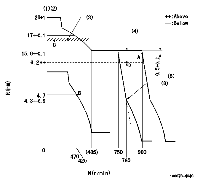
N:Pump speed
R:Rack position (mm)
(1)Target notch: K
(2)Tolerance for racks not indicated: +-0.05mm.
(3)Limit using excess fuel lever (boost pressure 0): L1
(4)Boost compensator stroke: BCL
(5)Rack difference between N = N1 and N = N2
(6)Idle sub spring setting: L2.
----------
K=4 L1=16.6+0.2mm BCL=4+-0.1mm N1=900r/min N2=850r/min L2=4.3-0.5mm
----------
----------
K=4 L1=16.6+0.2mm BCL=4+-0.1mm N1=900r/min N2=850r/min L2=4.3-0.5mm
----------
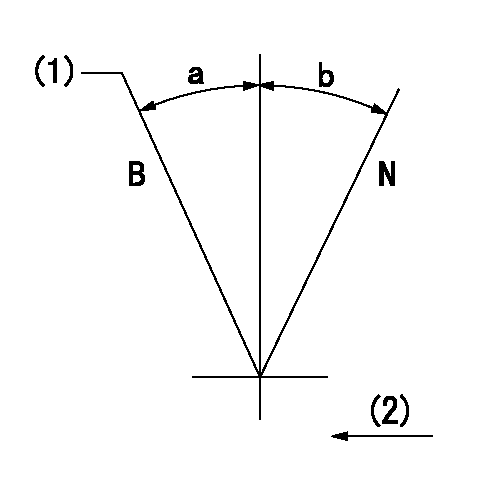
Speed control lever angle
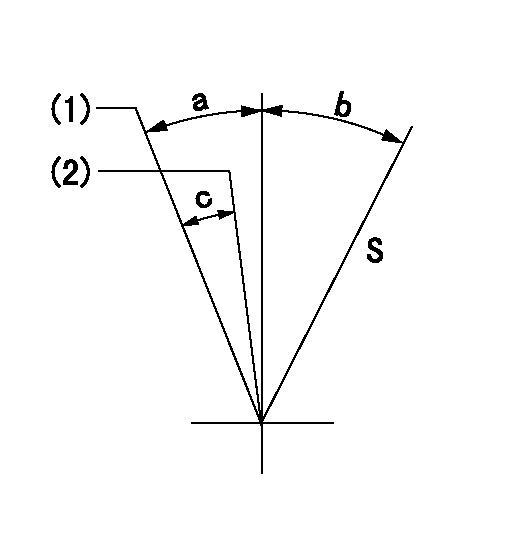
S:Stop
(1)Speed set at aa (setting at supply)
(2)When pump speed set at bb
----------
aa=900r/min bb=750r/min
----------
a=6deg+-5deg b=29deg+-3deg c=6deg+-5deg
----------
aa=900r/min bb=750r/min
----------
a=6deg+-5deg b=29deg+-3deg c=6deg+-5deg
0000000901
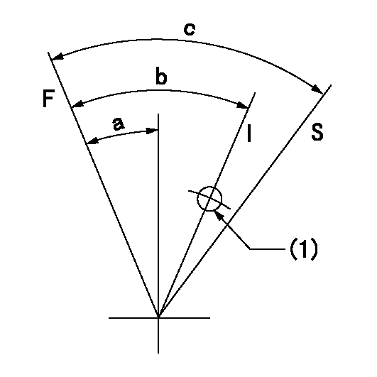
F:Full load
I:Idle
S:Stop
(1)Use the hole at R = aa
----------
aa=25mm
----------
a=26deg+-5deg b=36deg+-5deg c=53deg+-5deg
----------
aa=25mm
----------
a=26deg+-5deg b=36deg+-5deg c=53deg+-5deg
0000001101
N:Normal
B:When boosted
(1)Rack position = aa at boost pressure = 0.
(2)Drive side
----------
aa=16.6+0.2mm
----------
a=(15deg)+-5deg b=(15deg)
----------
aa=16.6+0.2mm
----------
a=(15deg)+-5deg b=(15deg)
Timing setting

(1)Pump vertical direction
(2)Coupling's key groove position at No 1 cylinder's beginning of injection
(3)-
(4)-
----------
----------
a=(95deg)
----------
----------
a=(95deg)
Information:
Solenoid Valve Replacement
Make reference to the at the beginning of the Testing And Adjusting section.
This procedure assumes that the ether cylinder mounted on the failed solenoid valve may still contain ether and is usable. If the ether cylinder is empty and needs replacement, complete this procedure and then follow the normal cylinder replacement procedure. See Ether Cylinder Replacement.
Solenoid Valve Assembly The solenoid valve itself is not serviceable. The complete solenoid valve assembly must be replaced. This includes the mounting bracket.1. Turn the disconnect switch to the OFF position. 2. Remove the ether cylinder from failed solenoid valve (1).3. Disconnect ether line (2) from the outlet of failed solenoid valve (1).4. Disconnect (unplug) solenoid valve harness connector (3). 5. Remove the reset switch bracket from the solenoid valve by removing two bolts (4). Leave the reset switch and wires intact on the bracket.6. Remove the solenoid valve assembly, which includes the mounting bracket, from the vehicle by removing two bolts (5).
Orifice Fitting And Filter7. Prepare the new solenoid valve for installation by installing a new orifice fitting and filter.
The orifice fitting has left-hand threads.
8. Attach the new solenoid valve and reset switch bracket to the vehicle. Tighten top two bolts (5) and leave lower two bolts (4) loose.
Gasket Filter9. Install a new gasket filter into the inlet of the solenoid valve.10. Install the same ether cylinder. See within Ether Cylinder Replacement. Hand tighten the ether cylinder to the solenoid valve. 11. Adjust the reset switch bracket such that reset switch button (6) depresses as much as possible while contacting the ether cylinder. Tighten lower two bolts (4) which fasten the reset switch bracket and solenoid valve to the vehicle. The reset switch must be adjusted correctly in order for the ether injection system to operate properly. The function of the reset switch is: to be OPEN (depressed switch button) when an ether cylinder is installed, and to be CLOSED (extended switch button) when the ether cylinder is removed. Ether injection is disabled when an ether cylinder is removed (reset switch closed).12. Verify that the reset switch is OPEN by continuity checking between the pin and socket in harness plug (7) of the reset switch. There should be no continuity.13. Reconnect the harnesses to the solenoid valve and the reset switch. Turn the disconnect switch to the ON position.Ether Cylinder Removal
Non-Empty Cylinders
During maintenance or servicing, the ether cylinders may need to be removed when they are not empty (for example, the cylinders may have to be removed to gain access to some other item requiring service). Under these conditions, it is desirable to remove and reinstall the ether cylinders without disturbing the "ether cylinder timers" within the ether injection control. This procedure allows the same ether cylinder to be reinstalled after it has been removed. Normal ether cylinder replacement is performed when the ether cylinder is empty. Normal removal of an empty ether cylinder resets the "ether cylinder timers" within the ether injection control. See Ether Cylinder Replacement. Failure to