Information injection-pump assembly
ZEXEL
106673-4020
1066734020
MITSUBISHI-HEAV
3626550190
3626550190
Rating:
Service parts 106673-4020 INJECTION-PUMP ASSEMBLY:
1.
_
7.
COUPLING PLATE
8.
_
9.
_
11.
Nozzle and Holder
36261-33010
12.
Open Pre:MPa(Kqf/cm2)
21.6{220}
15.
NOZZLE SET
Include in #1:
106673-4020
as INJECTION-PUMP ASSEMBLY
Cross reference number
ZEXEL
106673-4020
1066734020
MITSUBISHI-HEAV
3626550190
3626550190
Zexel num
Bosch num
Firm num
Name
Calibration Data:
Adjustment conditions
Test oil
1404 Test oil ISO4113 or {SAEJ967d}
1404 Test oil ISO4113 or {SAEJ967d}
Test oil temperature
degC
40
40
45
Nozzle and nozzle holder
105780-8130
Bosch type code
EFEP215A
Nozzle
105780-0050
Bosch type code
DN6TD119NP1T
Nozzle holder
105780-2090
Bosch type code
EFEP215
Opening pressure
MPa
17.2
Opening pressure
kgf/cm2
175
Injection pipe
Outer diameter - inner diameter - length (mm) mm 8-3-600
Outer diameter - inner diameter - length (mm) mm 8-3-600
Overflow valve
131424-7420
Overflow valve opening pressure
kPa
255
221
289
Overflow valve opening pressure
kgf/cm2
2.6
2.25
2.95
Tester oil delivery pressure
kPa
157
157
157
Tester oil delivery pressure
kgf/cm2
1.6
1.6
1.6
Direction of rotation (viewed from drive side)
Right R
Right R
Injection timing adjustment
Direction of rotation (viewed from drive side)
Right R
Right R
Injection order
1-5-3-6-
2-4
Pre-stroke
mm
3.9
3.85
3.95
Beginning of injection position
Governor side NO.1
Governor side NO.1
Difference between angles 1
Cal 1-5 deg. 60 59.5 60.5
Cal 1-5 deg. 60 59.5 60.5
Difference between angles 2
Cal 1-3 deg. 120 119.5 120.5
Cal 1-3 deg. 120 119.5 120.5
Difference between angles 3
Cal 1-6 deg. 180 179.5 180.5
Cal 1-6 deg. 180 179.5 180.5
Difference between angles 4
Cyl.1-2 deg. 240 239.5 240.5
Cyl.1-2 deg. 240 239.5 240.5
Difference between angles 5
Cal 1-4 deg. 300 299.5 300.5
Cal 1-4 deg. 300 299.5 300.5
Injection quantity adjustment
Adjusting point
A
Rack position
15.6
Pump speed
r/min
900
900
900
Average injection quantity
mm3/st.
333
326
340
Max. variation between cylinders
%
0
-3
3
Basic
*
Fixing the rack
*
Boost pressure
kPa
93.3
93.3
Boost pressure
mmHg
700
700
Injection quantity adjustment_02
Adjusting point
B
Rack position
4.7+-0.5
Pump speed
r/min
425
425
425
Average injection quantity
mm3/st.
32.2
29.7
34.7
Max. variation between cylinders
%
0
-10
10
Fixing the rack
*
Boost pressure
kPa
0
0
0
Boost pressure
mmHg
0
0
0
Boost compensator adjustment
Pump speed
r/min
850
850
850
Rack position
R1-4
Boost pressure
kPa
40
37.3
42.7
Boost pressure
mmHg
300
280
320
Boost compensator adjustment_02
Pump speed
r/min
850
850
850
Rack position
R1(16.2)
Boost pressure
kPa
80
73.3
86.7
Boost pressure
mmHg
600
550
650
Timer adjustment
Pump speed
r/min
900++
Advance angle
deg.
0
0
0
Remarks
Do not advance until starting N = 900.
Do not advance until starting N = 900.
Timer adjustment_02
Pump speed
r/min
-
Advance angle
deg.
1
1
1
Remarks
Measure the actual speed, stop
Measure the actual speed, stop
Test data Ex:
Governor adjustment
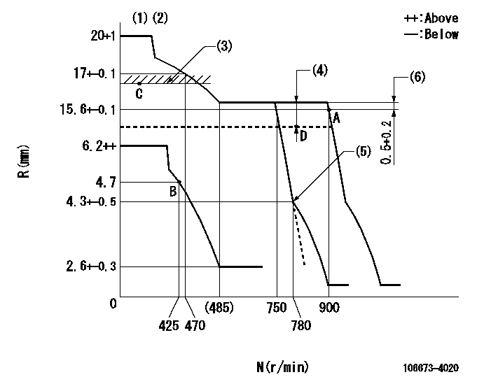
N:Pump speed
R:Rack position (mm)
(1)Target notch: K
(2)Tolerance for racks not indicated: +-0.05mm.
(3)Limit using excess fuel lever (boost pressure 0): L1
(4)Boost compensator stroke: BCL
(5)Idle sub spring setting: L2.
(6)Rack difference between N = N1 and N = N2
----------
K=4 L1=16.6+0.2mm BCL=4+-0.1mm L2=4.3-0.5mm N1=900r/min N2=850r/min
----------
----------
K=4 L1=16.6+0.2mm BCL=4+-0.1mm L2=4.3-0.5mm N1=900r/min N2=850r/min
----------
Speed control lever angle
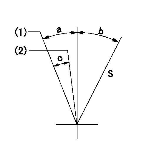
S:Stop
(1)Speed set at aa (setting at supply)
(2)When pump speed set at bb
----------
aa=900r/min bb=750r/min
----------
a=6deg+-5deg b=29deg+-3deg c=6deg+-5deg
----------
aa=900r/min bb=750r/min
----------
a=6deg+-5deg b=29deg+-3deg c=6deg+-5deg
0000000901
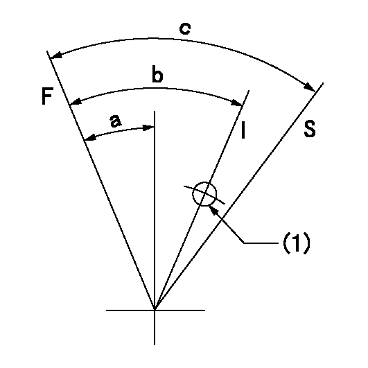
F:Full load
I:Idle
S:Stop
(1)Use the hole at R = aa
----------
aa=25mm
----------
a=26deg+-5deg b=36deg+-5deg c=53deg+-5deg
----------
aa=25mm
----------
a=26deg+-5deg b=36deg+-5deg c=53deg+-5deg
0000001101
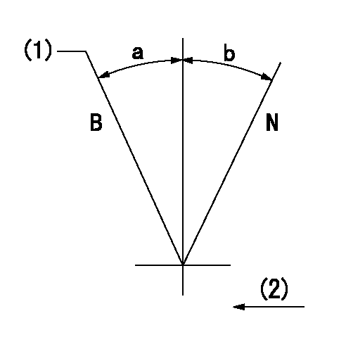
N:Normal
B:When boosted
(1)Rack position = aa at boost pressure 0.
(2)Drive side
----------
aa=16.6+0.2mm
----------
a=(15deg)+-5deg b=(15deg)
----------
aa=16.6+0.2mm
----------
a=(15deg)+-5deg b=(15deg)
Timing setting
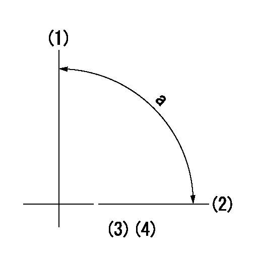
(1)Pump vertical direction
(2)Coupling's key groove position at No 1 cylinder's beginning of injection
(3)-
(4)-
----------
----------
a=(90deg)
----------
----------
a=(90deg)
Information:
1. Poor Quality Fuel If poor or low quality fuel is suspected, use a source of known good quality fuel, prime and start the engine. If the problem is resolved, drain the complete fuel system, replace the fuel filter, and add fuel recommended by Caterpillar.2. Low Fuel Pressure Measure the fuel transfer pump pressure at rated engine rpm. The 1U5470 Engine Pressure Group can be used to measure the fuel transfer pump pressure. The 1U5470 Engine Pressure Group has a gauge to read fuel pressure to the fuel supply manifold. Special Instruction, Form No. SEHS8907 is with the tool group and gives information for its use. The ECAP or the DDT can also be used to check the fuel transfer pump pressure.If the fuel transfer pump pressure is below 445 kPa (65 psi) at rated rpm, check for: * Restrictions in the low pressure fuel system (plugged fuel filter, collapsed hoses, etc).* Air in the fuel.* Fuel transfer pump wear or damage. Refer to Specifications, 3176 Vehicular Diesel Engine, Form No. SENR4965.* Excessive fuel return to the tank due to a malfunction of the fuel pressure regulating valve in the siphon block.3. Air In Fuel System Disconnect the fuel return line at the tank. Place this end of the line in a container of fuel to see if air bubbles are present while the engine is running. If air bubbles are observed, check for loose fittings or line leaks between the fuel tank and the fuel transfer pump. If leaks are found, tighten the connections or replace the line(s).To remove air from the engine fuel system: With the engine off, loosen the fuel return line fitting at the fuel manifold. Operate the fuel priming pump until the flow of fuel is free of air. Tighten the return line fitting, fasten the priming pump, and start the engine. If the engine still does not run smooth or produces a lot of white smoke, apply 35 kPa (5 psi) of air pressure to the fuel tank to force fuel through the system.
Do not use more than 55 kPa (8 psi) of air pressure in the fuel tank or damage to the tank may result.
Check the fuel return line for restriction. Replace if it is plugged.4. Injector Not Seated Properly Leakage due to a loose injector or inadequate injector/sleeve sealing can cause combustion gas to enter the fuel supply manifold. Inspect and repair as necessary the sealing surface (seat) of the injector sleeve. The injector sealing surface (seat) must be free of scratches or evidence of a combustion leak (carbon). If it is necessary to rework (ream) or replace the sleeve use 4C4054 Tool Group and refer to Special Instruction, Form No. SEHS9246, Using The 4C4054 Unit Injector Sleeve Replacement Tool Group. Torque the fuel injector hold down bolt to 30 7 N m (22 5 lb ft).5. Defective Unit Injectors A defective unit injector can be found using the Electronic Control Analyzer and Programmer (ECAP) and the