Information injection-pump assembly
BOSCH
9 400 617 308
9400617308
ZEXEL
106673-4000
1066734000
Rating:
Cross reference number
BOSCH
9 400 617 308
9400617308
ZEXEL
106673-4000
1066734000
Zexel num
Bosch num
Firm num
Name
106673-4000
9 400 617 308
HYUNDAI
INJECTION-PUMP ASSEMBLY
6D22TC * K 14CA PE6P,6PD PE
6D22TC * K 14CA PE6P,6PD PE
Calibration Data:
Adjustment conditions
Test oil
1404 Test oil ISO4113 or {SAEJ967d}
1404 Test oil ISO4113 or {SAEJ967d}
Test oil temperature
degC
40
40
45
Nozzle and nozzle holder
105780-8140
Bosch type code
EF8511/9A
Nozzle
105780-0000
Bosch type code
DN12SD12T
Nozzle holder
105780-2080
Bosch type code
EF8511/9
Opening pressure
MPa
17.2
Opening pressure
kgf/cm2
175
Injection pipe
Outer diameter - inner diameter - length (mm) mm 8-3-600
Outer diameter - inner diameter - length (mm) mm 8-3-600
Overflow valve
131424-4620
Overflow valve opening pressure
kPa
255
221
289
Overflow valve opening pressure
kgf/cm2
2.6
2.25
2.95
Tester oil delivery pressure
kPa
157
157
157
Tester oil delivery pressure
kgf/cm2
1.6
1.6
1.6
Direction of rotation (viewed from drive side)
Right R
Right R
Injection timing adjustment
Direction of rotation (viewed from drive side)
Right R
Right R
Injection order
1-5-3-6-
2-4
Pre-stroke
mm
4.8
4.75
4.85
Beginning of injection position
Governor side NO.1
Governor side NO.1
Difference between angles 1
Cal 1-5 deg. 60 59.5 60.5
Cal 1-5 deg. 60 59.5 60.5
Difference between angles 2
Cal 1-3 deg. 120 119.5 120.5
Cal 1-3 deg. 120 119.5 120.5
Difference between angles 3
Cal 1-6 deg. 180 179.5 180.5
Cal 1-6 deg. 180 179.5 180.5
Difference between angles 4
Cyl.1-2 deg. 240 239.5 240.5
Cyl.1-2 deg. 240 239.5 240.5
Difference between angles 5
Cal 1-4 deg. 300 299.5 300.5
Cal 1-4 deg. 300 299.5 300.5
Injection quantity adjustment
Adjusting point
A
Rack position
10.5
Pump speed
r/min
800
800
800
Average injection quantity
mm3/st.
145.3
142.3
148.3
Max. variation between cylinders
%
0
-3
3
Basic
*
Fixing the lever
*
Injection quantity adjustment_02
Adjusting point
B
Rack position
5.8+-0.5
Pump speed
r/min
275
275
275
Average injection quantity
mm3/st.
15
12.4
17.6
Fixing the rack
*
Remarks
(check)
(check)
Injection quantity adjustment_03
Adjusting point
C
Rack position
5.2+-0.5
Pump speed
r/min
500
500
500
Average injection quantity
mm3/st.
15
12.4
17.6
Max. variation between cylinders
%
0
-15
15
Fixing the rack
*
Injection quantity adjustment_04
Adjusting point
D
Rack position
-
Pump speed
r/min
100
100
100
Average injection quantity
mm3/st.
142
122
162
Fixing the lever
*
Rack limit
*
Timer adjustment
Pump speed
r/min
1050--
Advance angle
deg.
0
0
0
Remarks
Start
Start
Timer adjustment_02
Pump speed
r/min
1000
Advance angle
deg.
0.5
Timer adjustment_03
Pump speed
r/min
1100
Advance angle
deg.
1.5
1
2
Timer adjustment_04
Pump speed
r/min
-
Advance angle
deg.
2
2
2
Remarks
Measure the actual speed, stop
Measure the actual speed, stop
Test data Ex:
Governor adjustment
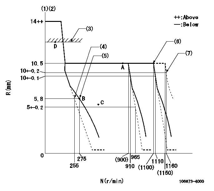
N:Pump speed
R:Rack position (mm)
(1)Target notch: K
(2)Tolerance for racks not indicated: +-0.05mm.
(3)RACK LIMIT
(4)Main spring setting
(5)Set idle sub-spring
(6)Torque spring does not operate.
(7)At delivery
----------
K=7
----------
----------
K=7
----------
Speed control lever angle
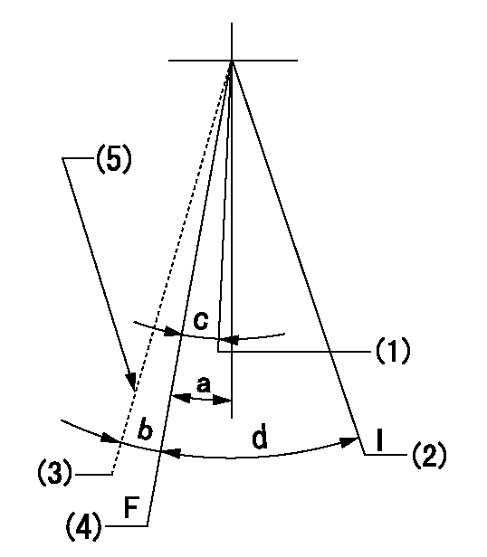
F:Full speed
I:Idle
(1)Set the pump speed at aa
(2)Stopper bolt setting
(3)At delivery
(4)Set the pump speed at bb.
(5)Stopper bolt setting
----------
aa=910r/min bb=1110r/min
----------
a=9deg+-5deg b=(2deg) c=7deg+-5deg d=29deg+-5deg
----------
aa=910r/min bb=1110r/min
----------
a=9deg+-5deg b=(2deg) c=7deg+-5deg d=29deg+-5deg
Stop lever angle

N:Pump normal
S:Stop the pump.
----------
----------
a=19deg+-5deg b=53deg+-5deg
----------
----------
a=19deg+-5deg b=53deg+-5deg
Timing setting

(1)Pump vertical direction
(2)Coupling's key groove position at No 1 cylinder's beginning of injection
(3)-
(4)-
----------
----------
a=(7deg)
----------
----------
a=(7deg)
Information:
External LeaksPressurize the cooling system using the 9S8140 Cooling System Pressurizing Pump Group and check the following:1. Leaks In Hoses Or Connections Check all hoses and connections for visual signs of leakage. If no leaks are found, look for damage to hoses or loose hose clamps. Also, check for leaks in accessories such as fuel heaters and transmission oil coolers.2. Leaks In The Radiator3. Leaks In The Heater4. Leaks In The Water Pump Check the water pump for leaks before starting the engine, then start the engine and look for leaks. If there are leaks at the water pump, repair the pump or install a new pump.5. Cylinder Head Gasket Leaks Look for leaks along the surface of the cylinder head gasket. If leaks are found, remove the cylinder head and install a new head gasket. Coolant Leaks At The Overflow Tube6. Defective Pressure Cap Or Relief Valve Check the sealing surfaces of the pressure cap and the radiator to be sure the cap is sealing correctly. Check the opening pressure and sealing ability of the pressure cap or relief valve with the 9S8140 Cooling System Pressurizing Pump Group.7. Engine Runs Too Hot If coolant temperature is too high, pressure will be high enough to move the cap off of the sealing surface in the radiator and cause coolant loss through the overflow tube. If this occurs, refer to the portion, Overheating, of the topic, Abnormal Cooling System.8. Air/Combustion Gas In The Cooling System Air/Combustion Gas in the cooling system reduces the heat transfer from hot engine parts to the coolant and causes low coolant flow. The most common causes of air are: * Improper filling of the cooling system trapping air in the system.* Combustion gas leaking into the system. If air/combustion gas is present in the cooling system, the engine should be checked for internal cracks (cylinder head, injector sleeve, cylinder liner) or for a defective cylinder head gasket.The cooling system can be checked for air using the BOTTLE TEST. The equipment needed to do this test is a one pint bottle, a bucket of water, and a hose which will fit the end of the overflow pipe of the radiator. Before testing, be sure the cooling system is filled correctly. Use a wire to hold the relief valve in the radiator cap open. Put the hose over the end of the overflow pipe. Start the engine and operate it at high idle rpm for a minimum of five minutes after the engine is at normal operating temperature. After five or more minutes at operating temperature, place the loose end of the hose in the bottle filled with water. If the water gets out of the bottle in less than forty seconds, there is too much exhaust gas leakage into the cooling system. Find the cause of the air or gas getting into the cooling system and correct as necessary. Internal LeakageIf coolant is found in the engine oil check the following internal components
Have questions with 106673-4000?
Group cross 106673-4000 ZEXEL
Hyundai
106673-4000
9 400 617 308
INJECTION-PUMP ASSEMBLY
6D22TC
6D22TC