Information injection-pump assembly
BOSCH
9 400 619 420
9400619420
ZEXEL
106673-3390
1066733390
HINO
220206480A
220206480a
Rating:
Service parts 106673-3390 INJECTION-PUMP ASSEMBLY:
1.
_
7.
COUPLING PLATE
8.
_
9.
_
11.
Nozzle and Holder
12.
Open Pre:MPa(Kqf/cm2)
14.
NOZZLE
Include in #1:
106673-3390
as INJECTION-PUMP ASSEMBLY
Cross reference number
BOSCH
9 400 619 420
9400619420
ZEXEL
106673-3390
1066733390
HINO
220206480A
220206480a
Zexel num
Bosch num
Firm num
Name
106673-3390
9 400 619 420
220206480A HINO
INJECTION-PUMP ASSEMBLY
K13C-TI K 14CA INJECTION PUMP ASSY PE6P,6PD PE
K13C-TI K 14CA INJECTION PUMP ASSY PE6P,6PD PE
Calibration Data:
Adjustment conditions
Test oil
1404 Test oil ISO4113 or {SAEJ967d}
1404 Test oil ISO4113 or {SAEJ967d}
Test oil temperature
degC
40
40
45
Nozzle and nozzle holder
105780-8140
Bosch type code
EF8511/9A
Nozzle
105780-0000
Bosch type code
DN12SD12T
Nozzle holder
105780-2080
Bosch type code
EF8511/9
Opening pressure
MPa
17.2
Opening pressure
kgf/cm2
175
Injection pipe
Outer diameter - inner diameter - length (mm) mm 8-3-600
Outer diameter - inner diameter - length (mm) mm 8-3-600
Overflow valve
131424-3420
Overflow valve opening pressure
kPa
255
221
289
Overflow valve opening pressure
kgf/cm2
2.6
2.25
2.95
Tester oil delivery pressure
kPa
255
255
255
Tester oil delivery pressure
kgf/cm2
2.6
2.6
2.6
Direction of rotation (viewed from drive side)
Left L
Left L
Injection timing adjustment
Direction of rotation (viewed from drive side)
Left L
Left L
Injection order
1-4-2-6-
3-5
Pre-stroke
mm
3.9
3.84
3.9
Beginning of injection position
Drive side NO.1
Drive side NO.1
Difference between angles 1
Cal 1-4 deg. 60 59.75 60.25
Cal 1-4 deg. 60 59.75 60.25
Difference between angles 2
Cyl.1-2 deg. 120 119.75 120.25
Cyl.1-2 deg. 120 119.75 120.25
Difference between angles 3
Cal 1-6 deg. 180 179.75 180.25
Cal 1-6 deg. 180 179.75 180.25
Difference between angles 4
Cal 1-3 deg. 240 239.75 240.25
Cal 1-3 deg. 240 239.75 240.25
Difference between angles 5
Cal 1-5 deg. 300 299.75 300.25
Cal 1-5 deg. 300 299.75 300.25
Injection quantity adjustment
Adjusting point
A
Rack position
12.2
Pump speed
r/min
1000
1000
1000
Average injection quantity
mm3/st.
187
185
189
Max. variation between cylinders
%
0
-2
2
Basic
*
Fixing the lever
*
Boost pressure
kPa
57.3
57.3
Boost pressure
mmHg
430
430
Injection quantity adjustment_02
Adjusting point
-
Rack position
7.2+-0.5
Pump speed
r/min
360
360
360
Average injection quantity
mm3/st.
14.8
11.8
17.8
Max. variation between cylinders
%
0
-15
15
Fixing the rack
*
Boost pressure
kPa
0
0
0
Boost pressure
mmHg
0
0
0
Remarks
Adjust only variation between cylinders; adjust governor according to governor specifications.
Adjust only variation between cylinders; adjust governor according to governor specifications.
Boost compensator adjustment
Pump speed
r/min
600
600
600
Rack position
10.95
Boost pressure
kPa
3.3
3.3
5.3
Boost pressure
mmHg
25
25
40
Boost compensator adjustment_02
Pump speed
r/min
600
600
600
Rack position
(13.2)
Boost pressure
kPa
44
44
44
Boost pressure
mmHg
330
330
330
Timer adjustment
Pump speed
r/min
750--
Advance angle
deg.
0
0
0
Load
3/4
Remarks
Start
Start
Timer adjustment_02
Pump speed
r/min
700
Advance angle
deg.
0.3
Load
3/4
Timer adjustment_03
Pump speed
r/min
1000
Advance angle
deg.
3.5
3.2
3.8
Load
4/4
Remarks
Finish
Finish
Test data Ex:
Governor adjustment
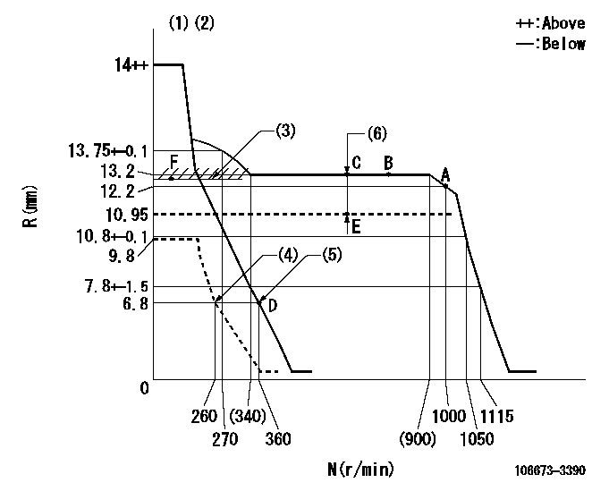
N:Pump speed
R:Rack position (mm)
(1)Notch fixed: K
(2)Tolerance for racks not indicated: +-0.05mm.
(3)Boost compensator excessive fuel lever at operation: L1 (at 0 boost pressure)
(4)Set idle sub-spring
(5)Main spring setting
(6)Boost compensator stroke: BCL
----------
K=13 L1=13.1+-0.1mm BCL=(2.25)mm
----------
----------
K=13 L1=13.1+-0.1mm BCL=(2.25)mm
----------
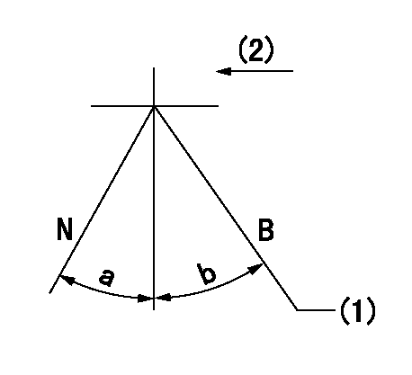
Speed control lever angle
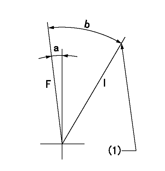
F:Full speed
I:Idle
(1)Stopper bolt setting
----------
----------
a=(7deg)+-5deg b=(23deg)+-5deg
----------
----------
a=(7deg)+-5deg b=(23deg)+-5deg
Stop lever angle
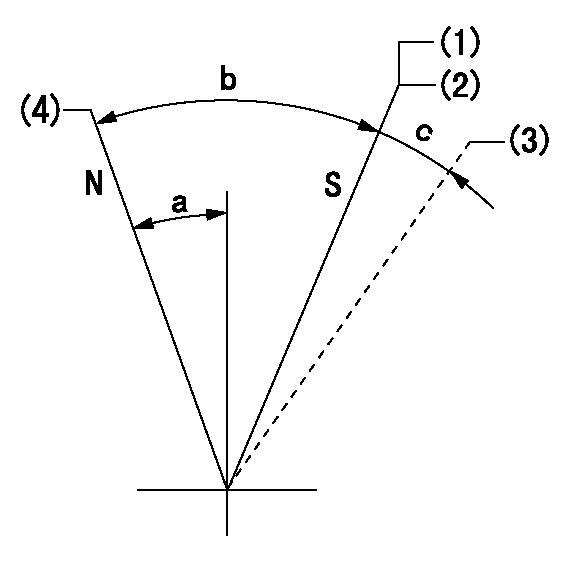
N:Pump normal
S:Stop the pump.
(1)Contacts inner boss.
(2)Rack position aa or less, pump speed bb
(3)Contacts outer boss.
(4)Normal
----------
aa=6.3mm bb=0r/min
----------
a=27deg+-5deg b=53deg+-5deg c=(11deg)
----------
aa=6.3mm bb=0r/min
----------
a=27deg+-5deg b=53deg+-5deg c=(11deg)
0000001101
N:Normal
B:When boosted
(1)Rack position = aa (at point F) at boost pressure = 0
(2)Drive side
----------
aa=13.1+-0.1mm
----------
a=(15deg) b=(8deg)
----------
aa=13.1+-0.1mm
----------
a=(15deg) b=(8deg)
Timing setting

(1)Pump vertical direction
(2)Coupling's key groove position at No 1 cylinder's beginning of injection
(3)-
(4)-
----------
----------
a=(1deg)
----------
----------
a=(1deg)
Information:
Overheating1. Defective Temperature Gauge If the temperature gauge shows that the coolant temperature is above normal and all other conditions indicate that conditions are normal, check the coolant temperature in another method, such as: * Read the coolant temperature with an ECAP or DDT.* Install an 8T0470 Thermistor Thermometer Group* Install a temperature sensitive tape.* Install a new gauge that is known to be good.2. Low Coolant Level Low coolant level can cause overheating to occur. Low coolant level can be caused by leaks in the cooling system or by improper filling of the radiator. With the engine cool, the coolant level should be at the low end of the fill neck on the radiator. If the coolant is below this level, a visual inspection should be done to see if any leaks can be seen. If nothing obvious is seen, refer to the topic Loss Of Coolant in this section. Fill the radiator according to recommendations in the Operation & Maintenance Manual.3. Dirty Radiator Check for debris between the fins of the radiator core which could restrict the free flow of air through the radiator core. Also check for debris or deposits on the inside of the core which could restrict the free flow of coolant through the radiator. Clean out any debris that is found.4. Fan Belt Slippage Check for proper fan speed with the fan engaged. Check the belt tension. Check the belt tensioner bearing and spring for proper operation. Check the belt and pulleys for lubricant contaminants which could cause belt slippage. Check the belt for hardening and glaze caused by heat and slippage. Repair or replace any defective parts that are detected.5. Defective Hoses Check the hoses for leaks, cuts and loose clamps. Check for any hoses that are collapsed or restricted that could cause a decrease in the amount of flow of coolant through the engine or radiator. Replace as necessary.6. Defective Pressure Cap Inspect the sealing surface of the pressure cap and the radiator. Look for any damage to the seal or the sealing surface. Remove any foreign material and replace any defective seals. Check the sealing pressure of the cap with the Cooling System Pressurization Pump Group, 9S8140. This will check the opening pressure of the cap. If the cap is defective, replace it.7. Defective Water Temperature Regulator If the water temperature regulator is not opening properly or if the seal is damaged, it can cause the engine to overheat. Check the water temperature regulator for proper operation according to the test procedure for the thermostat located in the Testing and Adjusting section of Systems Operation, Testing and Adjusting, Form No. SENR4964.8. Defective Water Pump Check the water pump impeller for damage or looseness on the shaft. Also, see the topic, Cooling System, in the Testing and Adjusting section of Systems Operation, Testing and Adjusting, Form No. SENR4964.9. Air/Combustion Gas In The Cooling System Air/Combustion Gas in the cooling system reduces the heat transfer from hot engine parts to
Have questions with 106673-3390?
Group cross 106673-3390 ZEXEL
Hino
Hino
106673-3390
9 400 619 420
220206480A
INJECTION-PUMP ASSEMBLY
K13C-TI
K13C-TI