Information injection-pump assembly
ZEXEL
106673-3331
1066733331
HINO
220205880A
220205880a
Rating:
Cross reference number
ZEXEL
106673-3331
1066733331
HINO
220205880A
220205880a
Zexel num
Bosch num
Firm num
Name
Calibration Data:
Adjustment conditions
Test oil
1404 Test oil ISO4113 or {SAEJ967d}
1404 Test oil ISO4113 or {SAEJ967d}
Test oil temperature
degC
40
40
45
Nozzle and nozzle holder
105780-8140
Bosch type code
EF8511/9A
Nozzle
105780-0000
Bosch type code
DN12SD12T
Nozzle holder
105780-2080
Bosch type code
EF8511/9
Opening pressure
MPa
17.2
Opening pressure
kgf/cm2
175
Injection pipe
Outer diameter - inner diameter - length (mm) mm 8-3-600
Outer diameter - inner diameter - length (mm) mm 8-3-600
Overflow valve
134424-0920
Overflow valve opening pressure
kPa
162
147
177
Overflow valve opening pressure
kgf/cm2
1.65
1.5
1.8
Tester oil delivery pressure
kPa
157
157
157
Tester oil delivery pressure
kgf/cm2
1.6
1.6
1.6
Direction of rotation (viewed from drive side)
Left L
Left L
Injection timing adjustment
Direction of rotation (viewed from drive side)
Left L
Left L
Injection order
1-4-2-6-
3-5
Pre-stroke
mm
3.3
3.2
3.3
Beginning of injection position
Drive side NO.1
Drive side NO.1
Difference between angles 1
Cal 1-4 deg. 60 59.5 60.5
Cal 1-4 deg. 60 59.5 60.5
Difference between angles 2
Cyl.1-2 deg. 120 119.5 120.5
Cyl.1-2 deg. 120 119.5 120.5
Difference between angles 3
Cal 1-6 deg. 180 179.5 180.5
Cal 1-6 deg. 180 179.5 180.5
Difference between angles 4
Cal 1-3 deg. 240 239.5 240.5
Cal 1-3 deg. 240 239.5 240.5
Difference between angles 5
Cal 1-5 deg. 300 299.5 300.5
Cal 1-5 deg. 300 299.5 300.5
Injection quantity adjustment
Adjusting point
A
Rack position
9.7
Pump speed
r/min
700
700
700
Average injection quantity
mm3/st.
138
135
141
Max. variation between cylinders
%
0
-4
4
Basic
*
Fixing the lever
*
Injection quantity adjustment_02
Adjusting point
C
Rack position
6.1+-0.5
Pump speed
r/min
360
360
360
Average injection quantity
mm3/st.
13.5
10.5
16.5
Max. variation between cylinders
%
0
-15
15
Fixing the rack
*
Injection quantity adjustment_03
Adjusting point
D
Rack position
-
Pump speed
r/min
100
100
100
Average injection quantity
mm3/st.
165
165
175
Fixing the lever
*
Rack limit
*
Timer adjustment
Pump speed
r/min
850--
Advance angle
deg.
0
0
0
Remarks
Start
Start
Timer adjustment_02
Pump speed
r/min
800
Advance angle
deg.
0.5
Timer adjustment_03
Pump speed
r/min
1100
Advance angle
deg.
2.5
2
3
Remarks
Finish
Finish
Test data Ex:
Governor adjustment
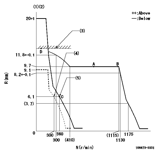
N:Pump speed
R:Rack position (mm)
(1)Notch fixed: K
(2)Tolerance for racks not indicated: +-0.05mm.
(3)RACK LIMIT
(4)Set idle sub-spring
(5)Main spring setting
----------
K=12
----------
----------
K=12
----------
Speed control lever angle

F:Full speed
I:Idle
(1)Stopper bolt setting
----------
----------
a=18deg+-5deg b=(33deg)+-5deg
----------
----------
a=18deg+-5deg b=(33deg)+-5deg
Stop lever angle

N:Pump normal
S:Stop the pump.
(1)Normal
----------
----------
a=27deg+-5deg b=53deg+-5deg
----------
----------
a=27deg+-5deg b=53deg+-5deg
Timing setting

(1)Pump vertical direction
(2)Coupling's key groove position at No 1 cylinder's beginning of injection
(3)-
(4)-
----------
----------
a=(0deg)
----------
----------
a=(0deg)
Information:
Piston Group.(1) Crater. The piston is a symmetrical piston with an "on center" crater. Thoroughly lubricate piston group 360° in zone (A) with clean engine oil prior to inserting into the block group.(2) Top piston ring. Install ring with side marked "UP-1" toward top of piston (yellow color stripe to right of ring end gap).Clearance between ends of piston ring when installed in a cylinder liner with a bore size of 125.000 mm (4.9213 in) ... 0.625 0.125 mm (.0250 .0050 in)Increase in clearance between ends of piston ring for each 0.03 mm (.001 in) increase in cylinder liner bore size ... 0.09 mm (.004 in)(3) Intermediate piston ring. Install ring with side marked "UP-2" toward top of piston (green color stripe to right of ring end gap).Width of groove in piston for intermediate ring (new) ... 3.061 0.013 mm (.1032 .0005 in)Depth of groove in piston for intermediate ring (new) ... 3.727 mm (.1467 in)Thickness of intermediate ring (new) ... 2.990 0.010 mm (.1177 .0004 in)Clearance between groove and intermediate ring (new) ... 0.048 to 0.094 mm (.0002 to .0037 in)Clearance between ends of piston ring when installed in a cylinder liner with a bore size of 125.000 mm (4.9213 in) ... 0.625 0.125 mm (.0250 .0050 in)Increase in clearance between ends of piston ring for each 0.03 mm (.001 in) increase in cylinder liner bore size ... 0.09 mm (.004 in)(4) Oil regulating piston ring. Oil ring spring ends to be assembled 180° from ring end gap (white colored portion of spring must be visible at ring end gap).Width of groove in piston for oil ring (new) ... 4.033 0.013 mm (.1588 .0005 in)Depth of groove in piston for oil ring (new) ... 3.727 mm (.1467 in)Thickness of oil ring (new) ... 3.987 0.013 mm (.1570 .0005 in)Clearance between groove and oil ring (new) ... 0.020 to 0.072 mm (.0008 to .0028 in)Clearance between ends of piston ring when installed in a cylinder liner with a bore size of 125.000 mm (4.9213 in) ... 0.55 0.15 mm (.022 .006 in)Increase in clearance between ends of piston ring for each 0.03 mm (.001 in) increase in cylinder liner bore size ... 0.09 mm (.004 in)After piston rings have been installed, rotate rings so the end gaps are 120° apart.(5) Crown assembly.(6) Piston pin bore diameter in piston skirt ... 51.15 0.15 mm (2.014 .006 in)Thoroughly lubricate piston pin with clean engine oil prior to inserting into piston group and rod assembly.(7) Piston skirt.