Information injection-pump assembly
ZEXEL
106673-3330
1066733330
Rating:
Cross reference number
ZEXEL
106673-3330
1066733330
Zexel num
Bosch num
Firm num
Name
106673-3330
INJECTION-PUMP ASSEMBLY
Calibration Data:
Adjustment conditions
Test oil
1404 Test oil ISO4113 or {SAEJ967d}
1404 Test oil ISO4113 or {SAEJ967d}
Test oil temperature
degC
40
40
45
Nozzle and nozzle holder
105780-8140
Bosch type code
EF8511/9A
Nozzle
105780-0000
Bosch type code
DN12SD12T
Nozzle holder
105780-2080
Bosch type code
EF8511/9
Opening pressure
MPa
17.2
Opening pressure
kgf/cm2
175
Injection pipe
Outer diameter - inner diameter - length (mm) mm 8-3-600
Outer diameter - inner diameter - length (mm) mm 8-3-600
Overflow valve
134424-0920
Overflow valve opening pressure
kPa
162
147
177
Overflow valve opening pressure
kgf/cm2
1.65
1.5
1.8
Tester oil delivery pressure
kPa
157
157
157
Tester oil delivery pressure
kgf/cm2
1.6
1.6
1.6
Direction of rotation (viewed from drive side)
Left L
Left L
Injection timing adjustment
Direction of rotation (viewed from drive side)
Left L
Left L
Injection order
1-4-2-6-
3-5
Pre-stroke
mm
3.3
3.2
3.3
Beginning of injection position
Drive side NO.1
Drive side NO.1
Difference between angles 1
Cal 1-4 deg. 60 59.5 60.5
Cal 1-4 deg. 60 59.5 60.5
Difference between angles 2
Cyl.1-2 deg. 120 119.5 120.5
Cyl.1-2 deg. 120 119.5 120.5
Difference between angles 3
Cal 1-6 deg. 180 179.5 180.5
Cal 1-6 deg. 180 179.5 180.5
Difference between angles 4
Cal 1-3 deg. 240 239.5 240.5
Cal 1-3 deg. 240 239.5 240.5
Difference between angles 5
Cal 1-5 deg. 300 299.5 300.5
Cal 1-5 deg. 300 299.5 300.5
Injection quantity adjustment
Adjusting point
A
Rack position
9.7
Pump speed
r/min
700
700
700
Average injection quantity
mm3/st.
138
135
141
Max. variation between cylinders
%
0
-4
4
Basic
*
Fixing the lever
*
Injection quantity adjustment_02
Adjusting point
C
Rack position
6.1+-0.5
Pump speed
r/min
360
360
360
Average injection quantity
mm3/st.
13.5
10.5
16.5
Max. variation between cylinders
%
0
-15
15
Fixing the rack
*
Injection quantity adjustment_03
Adjusting point
D
Rack position
-
Pump speed
r/min
100
100
100
Average injection quantity
mm3/st.
165
165
175
Fixing the lever
*
Rack limit
*
Timer adjustment
Pump speed
r/min
850--
Advance angle
deg.
0
0
0
Remarks
Start
Start
Timer adjustment_02
Pump speed
r/min
800
Advance angle
deg.
0.5
Timer adjustment_03
Pump speed
r/min
1100
Advance angle
deg.
2.5
2
3
Remarks
Finish
Finish
Test data Ex:
Governor adjustment
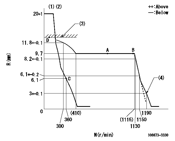
N:Pump speed
R:Rack position (mm)
(1)Target notch: K
(2)Tolerance for racks not indicated: +-0.05mm.
(3)RACK LIMIT
(4)Set idle sub-spring
----------
K=12
----------
----------
K=12
----------
Speed control lever angle

F:Full speed
I:Idle
(1)Stopper bolt setting
----------
----------
a=18deg+-5deg b=32deg+-5deg
----------
----------
a=18deg+-5deg b=32deg+-5deg
Stop lever angle

N:Pump normal
S:Stop the pump.
(1)Normal
----------
----------
a=27deg+-5deg b=53deg+-5deg
----------
----------
a=27deg+-5deg b=53deg+-5deg
Timing setting

(1)Pump vertical direction
(2)Coupling's key groove position at No 1 cylinder's beginning of injection
(3)-
(4)-
----------
----------
a=(0deg)
----------
----------
a=(0deg)
Information:
(1) Distance dowels extend past end surface of cylinder block ... 8.0 0.5 mm (.31 .02 in)(2) Bore diameter in cylinder block for the cylinder liners ... 136.00 0.03 mm (5.354 .001 in)(3) Distance dowels extend past end surface of cylinder block ... 8.0 0.5 mm (.31 .02 in) (4) Spacer block.(5) Height of dowels above top surface of spacer block and cylinder block ... 8.00 0.03 mm (.315 .001 in)(6) Cylinder Liner. Make reference to the procedure for checking Cylinder Liner Projection in Testing And Adjusting Section of Service Manual Form No. SENR4964.Cylinder liner projection above the top surface of the spacer block must be ... 0.12 0.08 mm (.005 .003 in)Apply 7M7260 Liquid Gasket as required to cylinder liner shoulder and cylinder block face joint of all liners. (7) Depth plug is to be installed (from end surface of cylinder block to top of plug) ... 1.25 0.25 mm (.049 .010 in)(8) Diameter of camshaft bores ... 75.000 0.025 mm (2.9530 .0010 in)(9) Oil cooling jet assembly. Tighten bolt that holds oil cooling jet to ... 25 7 N m (18 5 1b ft)(10) Width of main bearing cap ... 175.00 0.02 mm (6.8898 .0008 in) Width in cylinder block for main bearing cap ... 175.000 0.018 mm (6.8898 .0007 in)(11) Distance from centerline of crankshaft bore to top surface of cylinder block ... 265.0 mm (10.43 in)The flatness across the top contact surface of the block must be within 0.05 mm (.002 in) for any 150 mm (5.9 in) section of the surface.(12) Distance from centerline of crankshaft to bottom surface of cylinder block ... 120.0 mm (4.72 in)(13) Main bearing cap bolts. Install as follows: Main bearing caps shall be assembled with the part number towards the right side. Caps are to be identified by stamped numbers 1 thru 7 located on the bottom unmachined surface.Main bearing cap bolts are to be lubricated on threads and washer face with SAE 30 oil or molylube. Tighten bolts to 95 5 N m (70 4 lb ft) plus 90 5° additional turn prior to machining. Tighten bolts simultaneously or tighten both bolts to 95 N m (70 lb ft) before turning the additional 90°.(14) Bore in cylinder block for seven main bearings ... 108.000 0.013 mm (4.2520 .0005 in) All main bearing bore measurements are to be made before caps are disassembled.
Have questions with 106673-3330?
Group cross 106673-3330 ZEXEL
Hino
106673-3330
INJECTION-PUMP ASSEMBLY