Information injection-pump assembly
BOSCH
9 400 617 302
9400617302
ZEXEL
106673-3320
1066733320
HINO
220205960A
220205960a
Rating:
Cross reference number
BOSCH
9 400 617 302
9400617302
ZEXEL
106673-3320
1066733320
HINO
220205960A
220205960a
Zexel num
Bosch num
Firm num
Name
106673-3320
9 400 617 302
220205960A HINO
INJECTION-PUMP ASSEMBLY
K13C-T K 14CA INJECTION PUMP ASSY PE6P,6PD PE
K13C-T K 14CA INJECTION PUMP ASSY PE6P,6PD PE
Calibration Data:
Adjustment conditions
Test oil
1404 Test oil ISO4113 or {SAEJ967d}
1404 Test oil ISO4113 or {SAEJ967d}
Test oil temperature
degC
40
40
45
Nozzle and nozzle holder
105780-8140
Bosch type code
EF8511/9A
Nozzle
105780-0000
Bosch type code
DN12SD12T
Nozzle holder
105780-2080
Bosch type code
EF8511/9
Opening pressure
MPa
17.2
Opening pressure
kgf/cm2
175
Injection pipe
Outer diameter - inner diameter - length (mm) mm 8-3-600
Outer diameter - inner diameter - length (mm) mm 8-3-600
Overflow valve
134424-0920
Overflow valve opening pressure
kPa
162
147
177
Overflow valve opening pressure
kgf/cm2
1.65
1.5
1.8
Tester oil delivery pressure
kPa
157
157
157
Tester oil delivery pressure
kgf/cm2
1.6
1.6
1.6
Direction of rotation (viewed from drive side)
Left L
Left L
Injection timing adjustment
Direction of rotation (viewed from drive side)
Left L
Left L
Injection order
1-4-2-6-
3-5
Pre-stroke
mm
4.4
4.34
4.4
Beginning of injection position
Drive side NO.1
Drive side NO.1
Difference between angles 1
Cal 1-4 deg. 60 59.75 60.25
Cal 1-4 deg. 60 59.75 60.25
Difference between angles 2
Cyl.1-2 deg. 120 119.75 120.25
Cyl.1-2 deg. 120 119.75 120.25
Difference between angles 3
Cal 1-6 deg. 180 179.75 180.25
Cal 1-6 deg. 180 179.75 180.25
Difference between angles 4
Cal 1-3 deg. 240 239.75 240.25
Cal 1-3 deg. 240 239.75 240.25
Difference between angles 5
Cal 1-5 deg. 300 299.75 300.25
Cal 1-5 deg. 300 299.75 300.25
Injection quantity adjustment
Adjusting point
A
Rack position
9.6
Pump speed
r/min
900
900
900
Average injection quantity
mm3/st.
215
213
217
Max. variation between cylinders
%
0
-2
2
Basic
*
Fixing the rack
*
Boost pressure
kPa
32
32
Boost pressure
mmHg
240
240
Injection quantity adjustment_02
Adjusting point
C
Rack position
5.5+-0.5
Pump speed
r/min
600
600
600
Average injection quantity
mm3/st.
17.5
14.5
20.5
Fixing the rack
*
Boost pressure
kPa
0
0
0
Boost pressure
mmHg
0
0
0
Injection quantity adjustment_03
Adjusting point
D
Rack position
5.9+-0.5
Pump speed
r/min
938
938
938
Average injection quantity
mm3/st.
39.8
38.8
40.8
Max. variation between cylinders
%
0
-10
10
Fixing the lever
*
Boost pressure
kPa
0
0
0
Boost pressure
mmHg
0
0
0
Boost compensator adjustment
Pump speed
r/min
550
550
550
Rack position
R1-1.4
Boost pressure
kPa
4
2.7
5.3
Boost pressure
mmHg
30
20
40
Boost compensator adjustment_02
Pump speed
r/min
550
550
550
Rack position
R1(10.4)
Boost pressure
kPa
18.7
18.7
18.7
Boost pressure
mmHg
140
140
140
Timer adjustment
Pump speed
r/min
-
Advance angle
deg.
0
0
0
Remarks
Measure speed (beginning of operation).
Measure speed (beginning of operation).
Timer adjustment_02
Pump speed
r/min
-
Advance angle
deg.
2
1.7
2.3
Remarks
Measure the actual speed, stop
Measure the actual speed, stop
Test data Ex:
Governor adjustment
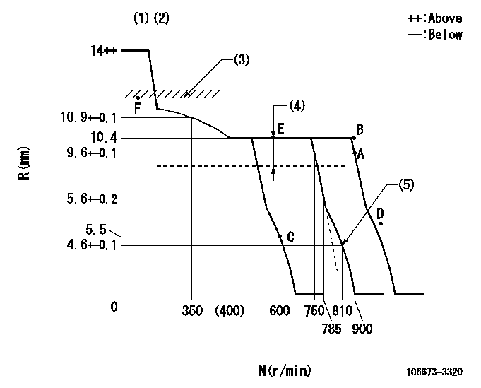
N:Pump speed
R:Rack position (mm)
(1)Target notch: K
(2)Tolerance for racks not indicated: +-0.05mm.
(3)Boost compensator excessive fuel lever at operation: L1 (at 0 boost pressure)
(4)Boost compensator stroke: BCL
(5)Set idle sub-spring
----------
K=6 L1=12+-0.1mm BCL=1.4+-0.1mm
----------
----------
K=6 L1=12+-0.1mm BCL=1.4+-0.1mm
----------
Speed control lever angle
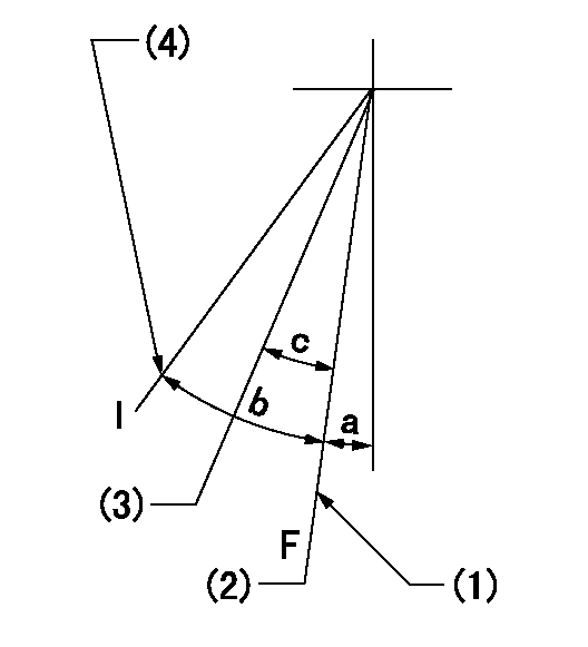
F:Full speed
I:Idle
(1)Stopper bolt setting
(2)Set the pump speed at aa. ( At delivery )
(3)When pump speed set at bb
(4)Stopper bolt setting
----------
aa=900r/min bb=750r/min
----------
a=(2deg)+-5deg b=(11deg)+-5deg c=(5deg)+-5deg
----------
aa=900r/min bb=750r/min
----------
a=(2deg)+-5deg b=(11deg)+-5deg c=(5deg)+-5deg
Stop lever angle
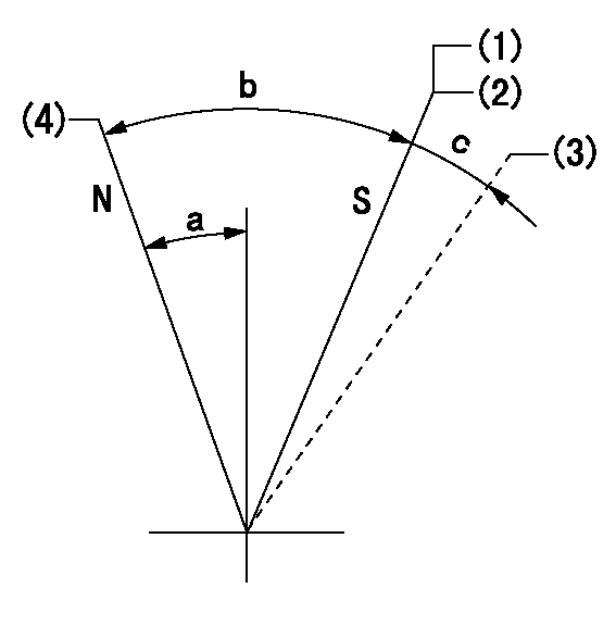
N:Pump normal
S:Stop the pump.
(1)Contacts inner boss.
(2)Rack position aa or less, pump speed bb
(3)Contacts outer boss.
(4)Normal
----------
aa=5mm bb=0r/min
----------
a=27deg+-5deg b=53deg+-5deg c=(11deg)
----------
aa=5mm bb=0r/min
----------
a=27deg+-5deg b=53deg+-5deg c=(11deg)
0000001101
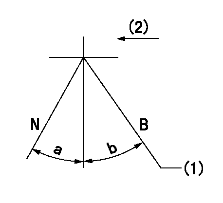
N:Normal
B:When boosted
(1)Rack position = aa (at point F) at boost pressure = 0
(2)Drive side
----------
aa=12+-0.1mm
----------
a=(15deg) b=(9deg)+-5deg
----------
aa=12+-0.1mm
----------
a=(15deg) b=(9deg)+-5deg
Timing setting

(1)Pump vertical direction
(2)Coupling's key groove position at No 1 cylinder's beginning of injection
(3)-
(4)-
----------
----------
a=(1deg)
----------
----------
a=(1deg)
Information:
(1) Oil cooler base bypass valve. Opening pressure ... 296 kPa (43 psi)(2) Base assembly. Tighten stud that holds filter assembly (3) to a torque of ... 68 7 N m (50 5 lb ft)(3) Filter assembly.(4) Cover. Tighten to a torque of ... 60 10 N m (44 7 lb ft)(5) Seal. Lubricate seal with lubricant being sealed.
Section A-A. Oil Filter Bypass Valve.The bypass opening pressure differential is 170 kPa (25 psi).(6) Seal.(7) Spring (8M3182): Assembled length ... 63.5 mm (2.50 in)Load assembled length ... 36.5 N (8.92 lb)Free length after test ... 91.7 mm (3.61 in)Outside diameter ... 20.6 mm (.81 in)(8) Seal.(9) Plunger.
Section B-B. Oil Pump Bypass Valve.(10) Spring (2N6005): Assembled length ... 96.52 mm (3.800 in)Load at assembled length ... 92.52 N (20.817 lb)Operating length (min) ... 45.72 mm (1.800 in)Load at min operating length ... 257.55 N (57.949 lb)Free length after test ... 124.71 mm (4.910 in)Outside diameter ... 21.84 mm (.860 in)(11) Valve.(12) Seal.(13) Seal.
Section C-C. High Pressure Relief Valve.The relief pressure is 696 kPa (101 psi).(14) Spacer.(15) Spring (1A2170): Assembled length ... 21.43 mm (.844 in)Load at assembled length ... 198.03 13.35 N (44.500 3.000 lb)Free length after test ... 31.00 mm (1.220 in)Outside diameter ... 19.60 mm (.772 in)(16) Seal.
Oil Cooler Bypass Valve.(17) Minimum stroke ... 8.4 mm (.33 in)(18) Length of valve fully compressed ... 44.2 1 mm (1.70 .04 in)(19) Length of valve fully extended ... 52.6 1 mm (2.10 .04 in)(B) Position "B".Valve Data: Start to close temperature ... 100 to 102.8° C (212 to 217° F)Position "B" temperature activation ... 111.1° C (232° F)Position "B" bypass opening pressure differential ... 155 17 kPa (22 2 psi)Fail safe activation temperature ... 126.7° C (260° F) Unit will stroke to and remain at position "B" at failsafe activation temperature.
Have questions with 106673-3320?
Group cross 106673-3320 ZEXEL
Hino
106673-3320
9 400 617 302
220205960A
INJECTION-PUMP ASSEMBLY
K13C-T
K13C-T