Information injection-pump assembly
BOSCH
9 400 617 301
9400617301
ZEXEL
106673-3310
1066733310
HINO
220205950A
220205950a
Rating:
Service parts 106673-3310 INJECTION-PUMP ASSEMBLY:
1.
_
7.
COUPLING PLATE
8.
_
9.
_
11.
Nozzle and Holder
12.
Open Pre:MPa(Kqf/cm2)
19.6(200)
15.
NOZZLE SET
Include in #1:
106673-3310
as INJECTION-PUMP ASSEMBLY
Cross reference number
BOSCH
9 400 617 301
9400617301
ZEXEL
106673-3310
1066733310
HINO
220205950A
220205950a
Zexel num
Bosch num
Firm num
Name
106673-3310
9 400 617 301
220205950A HINO
INJECTION-PUMP ASSEMBLY
K13D-T K 14CA INJECTION PUMP ASSY PE6P,6PD PE
K13D-T K 14CA INJECTION PUMP ASSY PE6P,6PD PE
Calibration Data:
Adjustment conditions
Test oil
1404 Test oil ISO4113 or {SAEJ967d}
1404 Test oil ISO4113 or {SAEJ967d}
Test oil temperature
degC
40
40
45
Nozzle and nozzle holder
105780-8140
Bosch type code
EF8511/9A
Nozzle
105780-0000
Bosch type code
DN12SD12T
Nozzle holder
105780-2080
Bosch type code
EF8511/9
Opening pressure
MPa
17.2
Opening pressure
kgf/cm2
175
Injection pipe
Outer diameter - inner diameter - length (mm) mm 8-3-600
Outer diameter - inner diameter - length (mm) mm 8-3-600
Overflow valve
134424-0920
Overflow valve opening pressure
kPa
162
147
177
Overflow valve opening pressure
kgf/cm2
1.65
1.5
1.8
Tester oil delivery pressure
kPa
157
157
157
Tester oil delivery pressure
kgf/cm2
1.6
1.6
1.6
Direction of rotation (viewed from drive side)
Left L
Left L
Injection timing adjustment
Direction of rotation (viewed from drive side)
Left L
Left L
Injection order
1-4-2-6-
3-5
Pre-stroke
mm
3.3
3.2
3.3
Beginning of injection position
Drive side NO.1
Drive side NO.1
Difference between angles 1
Cal 1-4 deg. 60 59.5 60.5
Cal 1-4 deg. 60 59.5 60.5
Difference between angles 2
Cyl.1-2 deg. 120 119.5 120.5
Cyl.1-2 deg. 120 119.5 120.5
Difference between angles 3
Cal 1-6 deg. 180 179.5 180.5
Cal 1-6 deg. 180 179.5 180.5
Difference between angles 4
Cal 1-3 deg. 240 239.5 240.5
Cal 1-3 deg. 240 239.5 240.5
Difference between angles 5
Cal 1-5 deg. 300 299.5 300.5
Cal 1-5 deg. 300 299.5 300.5
Injection quantity adjustment
Adjusting point
A
Rack position
10.3
Pump speed
r/min
900
900
900
Average injection quantity
mm3/st.
162
160
164
Max. variation between cylinders
%
0
-4
4
Basic
*
Fixing the rack
*
Injection quantity adjustment_02
Adjusting point
D
Rack position
6+-0.5
Pump speed
r/min
600
600
600
Average injection quantity
mm3/st.
9.5
8.5
10.5
Fixing the rack
*
Injection quantity adjustment_03
Adjusting point
E
Rack position
7+-0.5
Pump speed
r/min
935
935
935
Average injection quantity
mm3/st.
39
38
40
Max. variation between cylinders
%
0
-10
10
Fixing the rack
*
Injection quantity adjustment_04
Adjusting point
F
Rack position
11.1++
Pump speed
r/min
100
100
100
Average injection quantity
mm3/st.
215
210
220
Fixing the lever
*
Rack limit
*
Timer adjustment
Pump speed
r/min
(N1+50)-
-
Advance angle
deg.
0
0
0
Remarks
Start
Start
Timer adjustment_02
Pump speed
r/min
N1
Advance angle
deg.
0.5
Remarks
Measure the actual speed.
Measure the actual speed.
Timer adjustment_03
Pump speed
r/min
900
Remarks
Measure the actual advance angle.
Measure the actual advance angle.
Timer adjustment_04
Pump speed
r/min
-
Advance angle
deg.
1.5
1.5
1.5
Remarks
Measure the actual speed, stop
Measure the actual speed, stop
Test data Ex:
Governor adjustment
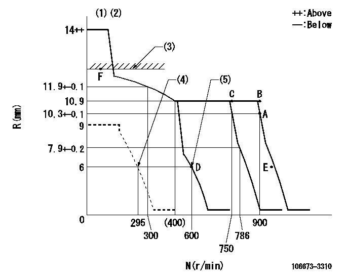
N:Pump speed
R:Rack position (mm)
(1)Target notch: K
(2)Tolerance for racks not indicated: +-0.05mm.
(3)RACK LIMIT
(4)Set idle sub-spring
(5)Main spring setting
----------
K=8
----------
----------
K=8
----------
Speed control lever angle
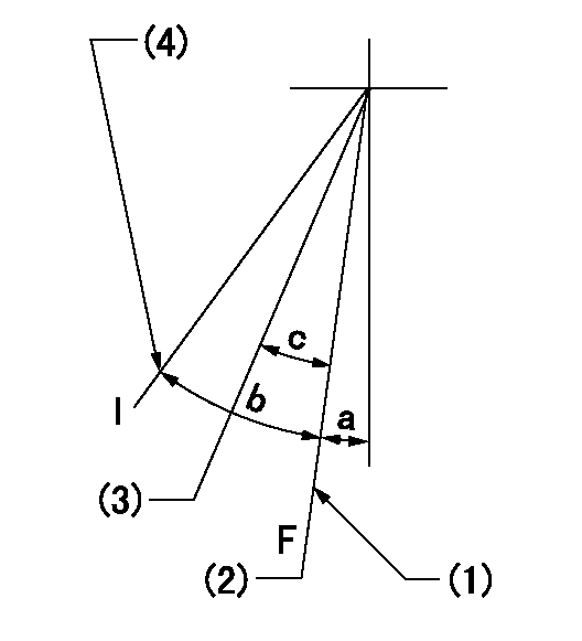
F:Full speed
I:Idle
(1)Stopper bolt setting
(2)Set the pump speed at aa. ( At delivery )
(3)When pump speed set at bb
(4)Stopper bolt setting
----------
aa=900r/min bb=750r/min
----------
a=1deg+-5deg b=12deg+-5deg c=5deg+-5deg
----------
aa=900r/min bb=750r/min
----------
a=1deg+-5deg b=12deg+-5deg c=5deg+-5deg
Stop lever angle
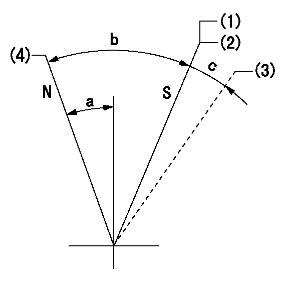
N:Pump normal
S:Stop the pump.
(1)Contacts inner boss.
(2)Rack position aa or less, pump speed bb
(3)Contacts outer boss.
(4)Normal
----------
aa=5.5mm bb=0r/min
----------
a=27deg+-5deg b=53deg+-5deg c=(11deg)
----------
aa=5.5mm bb=0r/min
----------
a=27deg+-5deg b=53deg+-5deg c=(11deg)
Timing setting

(1)Pump vertical direction
(2)Coupling's key groove position at No 1 cylinder's beginning of injection
(3)-
(4)-
----------
----------
a=(0deg)
----------
----------
a=(0deg)
Information:
Intake and exhaust valve stems are to be coated with 8T2998 Breakin Lubricant prior to installation in the cylinder head.(1) Intake valve.(2) Exhaust valve.(3) Height to top of valve guide ... 28.00 0.05 mm (1.102 .002 in)(4) Outer Valve Spring (7W7082): Assembled length ... 51.69 mm (2.035 in)Load at assembled length ... 240 24 N (54 5 lb)Operating length (min) ... 37.72 mm (1.485 in)Load at min operating length ... 650 32 N (146 7 lb)Free length after test ... 59.89 mm (2.358 in)Outside diameter ... 34.00 mm (1.339 in)(5) Inner Valve Spring (7W7083): Assembled length ... 49.19 mm (1.937 in)Load at assembled length ... 136 14 N (31 3 lb)Operating length (min) ... 35.22 mm (1.387 in)Load at min operating length ... 292 15 N (66 3 lb)Free length after test ... 61.39 mm (2.417 in)Outside diameter ... 23.24 mm (.915 in)(6) Diameter of valve stems (new) ... 9.441 0.008 mm (.3717 .0003 in)Use again minimum:7C1586 Exhaust ... 9.408 mm (.3704 in)7C5215 Intake ... 9.408 mm (.3704 in)Bore in valve guide with guide installed in the head (new) ... 9.484 0.026 mm (.3734 .0010 in)Use again dimension for valve guide bore ... 9.538 mm (.3755 in)(7) Diameter of valve head: Exhaust valve ... 42.00 0.13 mm (1.654 .005 in)Intake valve ... 45.00 0.13 mm (1.772 .005 in)(8) Angle of valve face: Angle of intake valve face ... 29 1/4 1/4°Angle of exhaust valve face ... 44 1/4 1/4° (9) Depth of bore in head for valve seat insert: Intake ... 15.00 0.10 mm (.591 .004 in)Exhaust ... 14.10 0.10 mm (.555 .004 in) Inserts to be shrunk by reduced temperature before being placed in counterbore.(10) Diameter of valve seat insert for intake valve ... 46.025 0.013 mm (1.8120 .0005 in) Bore in head for valve seat insert for intake valve ... 45.950 0.025 mm (1.8091 .0010 in)Diameter of valve seat insert for exhaust valve ... 43.400 0.015 mm (1.7086 .0006 in)Bore in head for valve seat insert for exhaust valve ... 43.320 0.025 mm (1.7055 .0009 in)(11) Angle of face of intake valve seat insert ... 30 1/4 1/2°Angle of face of exhaust valve seat insert ... 44 3/4 1/2°(12) "Use again" thickness of valve lip: Exhaust valve ... 2.03 mm (.080 in)Intake valve ... 2.51 mm (.099 in)
Have questions with 106673-3310?
Group cross 106673-3310 ZEXEL
Hino
106673-3310
9 400 617 301
220205950A
INJECTION-PUMP ASSEMBLY
K13D-T
K13D-T