Information injection-pump assembly
BOSCH
F 019 Z20 118
f019z20118
ZEXEL
106673-3233
1066733233
HINO
220205523A
220205523a
Rating:
Service parts 106673-3233 INJECTION-PUMP ASSEMBLY:
1.
_
7.
COUPLING PLATE
8.
_
9.
_
11.
Nozzle and Holder
236001860D
12.
Open Pre:MPa(Kqf/cm2)
21.6{220}
15.
NOZZLE SET
Include in #1:
106673-3233
as INJECTION-PUMP ASSEMBLY
Cross reference number
BOSCH
F 019 Z20 118
f019z20118
ZEXEL
106673-3233
1066733233
HINO
220205523A
220205523a
Zexel num
Bosch num
Firm num
Name
106673-3233
F 019 Z20 118
220205523A HINO
INJECTION-PUMP ASSEMBLY
K13D-T K 14CA INJECTION PUMP ASSY PE6P,6PD PE
K13D-T K 14CA INJECTION PUMP ASSY PE6P,6PD PE
Calibration Data:
Adjustment conditions
Test oil
1404 Test oil ISO4113 or {SAEJ967d}
1404 Test oil ISO4113 or {SAEJ967d}
Test oil temperature
degC
40
40
45
Nozzle and nozzle holder
105780-8140
Bosch type code
EF8511/9A
Nozzle
105780-0000
Bosch type code
DN12SD12T
Nozzle holder
105780-2080
Bosch type code
EF8511/9
Opening pressure
MPa
17.2
Opening pressure
kgf/cm2
175
Injection pipe
Outer diameter - inner diameter - length (mm) mm 8-3-600
Outer diameter - inner diameter - length (mm) mm 8-3-600
Overflow valve
134424-0920
Overflow valve opening pressure
kPa
162
147
177
Overflow valve opening pressure
kgf/cm2
1.65
1.5
1.8
Tester oil delivery pressure
kPa
157
157
157
Tester oil delivery pressure
kgf/cm2
1.6
1.6
1.6
Direction of rotation (viewed from drive side)
Left L
Left L
Injection timing adjustment
Direction of rotation (viewed from drive side)
Left L
Left L
Injection order
1-4-2-6-
3-5
Pre-stroke
mm
3.3
3.2
3.3
Beginning of injection position
Drive side NO.1
Drive side NO.1
Difference between angles 1
Cal 1-4 deg. 60 59.5 60.5
Cal 1-4 deg. 60 59.5 60.5
Difference between angles 2
Cyl.1-2 deg. 120 119.5 120.5
Cyl.1-2 deg. 120 119.5 120.5
Difference between angles 3
Cal 1-6 deg. 180 179.5 180.5
Cal 1-6 deg. 180 179.5 180.5
Difference between angles 4
Cal 1-3 deg. 240 239.5 240.5
Cal 1-3 deg. 240 239.5 240.5
Difference between angles 5
Cal 1-5 deg. 300 299.5 300.5
Cal 1-5 deg. 300 299.5 300.5
Injection quantity adjustment
Adjusting point
A
Rack position
8.8
Pump speed
r/min
800
800
800
Average injection quantity
mm3/st.
152.5
149.5
155.5
Max. variation between cylinders
%
0
-4
4
Basic
*
Fixing the lever
*
Injection quantity adjustment_02
Adjusting point
C
Rack position
6.8+-0.5
Pump speed
r/min
560
560
560
Average injection quantity
mm3/st.
50
48
52
Max. variation between cylinders
%
0
-15
15
Fixing the rack
*
Injection quantity adjustment_03
Adjusting point
D
Rack position
9++
Pump speed
r/min
100
100
100
Average injection quantity
mm3/st.
140
140
150
Fixing the lever
*
Rack limit
*
Timer adjustment
Pump speed
r/min
800--
Advance angle
deg.
0
0
0
Remarks
Start
Start
Timer adjustment_02
Pump speed
r/min
750
Advance angle
deg.
0.5
Timer adjustment_03
Pump speed
r/min
950
Advance angle
deg.
1.5
1
2
Remarks
Finish
Finish
Test data Ex:
Governor adjustment
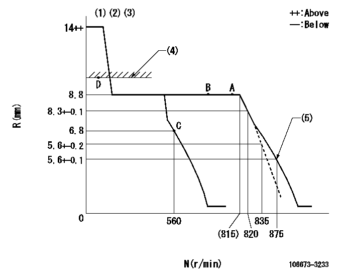
N:Pump speed
R:Rack position (mm)
(1)Target notch: K
(2)Tolerance for racks not indicated: +-0.05mm.
(3)Idle spring not operating.
(4)RACK LIMIT
(5)Set idle sub-spring
----------
K=9
----------
----------
K=9
----------
Speed control lever angle
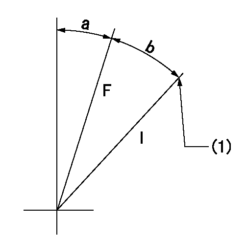
F:Full speed
I:Idle
(1)Stopper bolt setting
----------
----------
a=6deg+-5deg b=11deg+-5deg
----------
----------
a=6deg+-5deg b=11deg+-5deg
Stop lever angle
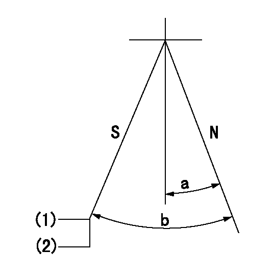
N:Pump normal
S:Stop the pump.
(1)Rack position aa or less, pump speed bb
(2)Normal stop
----------
aa=6.3mm bb=0r/min
----------
a=27deg+-5deg b=53deg+-5deg
----------
aa=6.3mm bb=0r/min
----------
a=27deg+-5deg b=53deg+-5deg
Timing setting

(1)Pump vertical direction
(2)Coupling's key groove position at No 1 cylinder's beginning of injection
(3)-
(4)-
----------
----------
a=(2deg)
----------
----------
a=(2deg)
Information:
Liner Projection Check
(1) 1P2402 Gauge Body. (2) 1P2403 Dial Indicator.3. Use body (1) and dial indicator (2) assembly to measure the cylinder liner (flange) projection in four locations around the liner. Do not measure liner projection from the flame ring (if equipped). Projection must be 0.10 mm (.004 in) above to 0.10 mm (.004 in) below the cylinder block face. The four measurements should not vary more than 0.03 mm (.001 in). The average projection between adjacent cylinders must not vary more than 0.03 mm (.001 in)Connecting Rods And Pistons
1. On T4.236 Engines, install the piston cooling jets and tighten the banjo bolt to 25 N m (20 lb ft). Adjust the piston cooling jets if necessary. See Piston Cooling Jet Position Check (T4.236 Engines) in Testing And Adjusting.2. Put a liberal amount of clean engine oil on the crankshaft journals, main bearings and thrust washers. Put the upper half of the main bearings and the crankshaft in position in the cylinder block.3. Slide the upper thrust washer halves into the recesses provided on either side of the center main bearing housing.4. Install the lower half of the main bearings into the main bearing caps. Install the main bearing caps to their respective positions. Position the lower thrust washer halves on either side of the center main bearing cap.5. The main bearing caps are numbered 1 through 5, beginning at the front of the block. Each cap is also marked with a serial number which is also stamped on the cylinder block bottom face. They all should read the same way.6. Install and tighten the main bearing bolts and tighten to a torque of 247 N m (180 lb ft).Use the 1Y7426 Piston Ring Compressor to remove or install piston rings.7. Put a liberal amount of clean engine oil in the bore of each cylinder and on the pistons before they are installed.8. Install the piston and connecting rod assemblies using the piston ring compressor as a guide. Be sure the piston and rod number are the same as for the cylinder bore each is installed in. The rod identification number must be opposite the camshaft. The word "Front" or arrow marked on the piston crown must be toward the front of the engine. If the piston crown is not marked, put the offset (narrowest distance between hole and edge of piston) of the piston toward the fuel injection pump side of the block.The connecting rod bearings must fit tightly in the bore of the rod. If bearing joints or backs are worn (fretted), check for bore size as this is an indication of wear because of looseness. Install the bearing cap with the numbers on the same side of the rod and cap.9. Install the connecting rod bolts so the flat on the bolt head is against the shoulder of the rod. Install new rod nuts. Tighten rod nuts to the torque that follows: Cadmium plated nuts silver color) ... 100 N m (75 lb ft)Phosphated nuts
Have questions with 106673-3233?
Group cross 106673-3233 ZEXEL
Hino
Hino
Hino
106673-3233
F 019 Z20 118
220205523A
INJECTION-PUMP ASSEMBLY
K13D-T
K13D-T
