Information injection-pump assembly
BOSCH
9 400 610 917
9400610917
ZEXEL
106673-3070
1066733070
Rating:
Service parts 106673-3070 INJECTION-PUMP ASSEMBLY:
1.
_
7.
COUPLING PLATE
8.
_
9.
_
11.
Nozzle and Holder
23600-2030A
12.
Open Pre:MPa(Kqf/cm2)
19.6{200}
15.
NOZZLE SET
Include in #1:
106673-3070
as INJECTION-PUMP ASSEMBLY
Cross reference number
BOSCH
9 400 610 917
9400610917
ZEXEL
106673-3070
1066733070
Zexel num
Bosch num
Firm num
Name
Calibration Data:
Adjustment conditions
Test oil
1404 Test oil ISO4113 or {SAEJ967d}
1404 Test oil ISO4113 or {SAEJ967d}
Test oil temperature
degC
40
40
45
Nozzle and nozzle holder
105780-8140
Bosch type code
EF8511/9A
Nozzle
105780-0000
Bosch type code
DN12SD12T
Nozzle holder
105780-2080
Bosch type code
EF8511/9
Opening pressure
MPa
17.2
Opening pressure
kgf/cm2
175
Injection pipe
Outer diameter - inner diameter - length (mm) mm 8-3-600
Outer diameter - inner diameter - length (mm) mm 8-3-600
Overflow valve
134424-0920
Overflow valve opening pressure
kPa
162
147
177
Overflow valve opening pressure
kgf/cm2
1.65
1.5
1.8
Tester oil delivery pressure
kPa
157
157
157
Tester oil delivery pressure
kgf/cm2
1.6
1.6
1.6
Direction of rotation (viewed from drive side)
Left L
Left L
Injection timing adjustment
Direction of rotation (viewed from drive side)
Left L
Left L
Injection order
1-4-2-6-
3-5
Pre-stroke
mm
3.3
3.2
3.3
Beginning of injection position
Drive side NO.1
Drive side NO.1
Difference between angles 1
Cal 1-4 deg. 60 59.5 60.5
Cal 1-4 deg. 60 59.5 60.5
Difference between angles 2
Cyl.1-2 deg. 120 119.5 120.5
Cyl.1-2 deg. 120 119.5 120.5
Difference between angles 3
Cal 1-6 deg. 180 179.5 180.5
Cal 1-6 deg. 180 179.5 180.5
Difference between angles 4
Cal 1-3 deg. 240 239.5 240.5
Cal 1-3 deg. 240 239.5 240.5
Difference between angles 5
Cal 1-5 deg. 300 299.5 300.5
Cal 1-5 deg. 300 299.5 300.5
Injection quantity adjustment
Adjusting point
A
Rack position
8.7
Pump speed
r/min
900
900
900
Average injection quantity
mm3/st.
157
155
159
Max. variation between cylinders
%
0
-4
4
Basic
*
Fixing the rack
*
Boost pressure
kPa
107
107
Boost pressure
mmHg
800
800
Injection quantity adjustment_02
Adjusting point
D
Rack position
4.7+-0.5
Pump speed
r/min
360
360
360
Average injection quantity
mm3/st.
9.5
6.5
12.5
Max. variation between cylinders
%
0
-15
15
Fixing the rack
*
Boost pressure
kPa
0
0
0
Boost pressure
mmHg
0
0
0
Boost compensator adjustment
Pump speed
r/min
600
600
600
Rack position
R1-0.8
Boost pressure
kPa
66.7
66.7
66.7
Boost pressure
mmHg
500
500
500
Boost compensator adjustment_02
Pump speed
r/min
600
600
600
Rack position
R1(9.3)
Boost pressure
kPa
93.3
86.6
100
Boost pressure
mmHg
700
650
750
Timer adjustment
Pump speed
r/min
(N1+50)-
-
Advance angle
deg.
0
0
0
Remarks
Start
Start
Timer adjustment_02
Pump speed
r/min
N1
Advance angle
deg.
0.5
Remarks
Measure the actual speed.
Measure the actual speed.
Timer adjustment_03
Pump speed
r/min
900
Remarks
Measure the actual advance angle.
Measure the actual advance angle.
Timer adjustment_04
Pump speed
r/min
-
Advance angle
deg.
1.5
1.5
1.5
Remarks
Measure the actual speed, stop
Measure the actual speed, stop
Test data Ex:
Governor adjustment
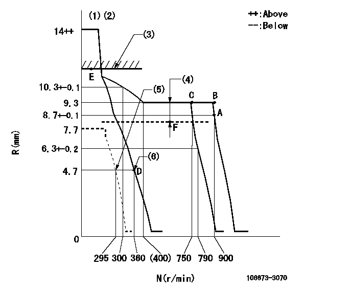
N:Pump speed
R:Rack position (mm)
(1)Target notch: K
(2)Tolerance for racks not indicated: +-0.05mm.
(3)Boost compensator excessive fuel lever at operation: L1 (at 0 boost pressure)
(4)Boost compensator stroke: BCL
(5)Set idle sub-spring
(6)Main spring setting
----------
K=9 L1=10.8+-0.1mm BCL=0.8+-0.1mm
----------
----------
K=9 L1=10.8+-0.1mm BCL=0.8+-0.1mm
----------
Speed control lever angle
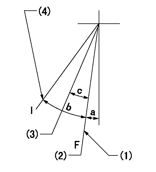
F:Full speed
I:Idle
(1)Stopper bolt setting
(2)Set the pump speed at aa. ( At delivery )
(3)When pump speed set at bb
(4)Stopper bolt setting
----------
aa=900r/min bb=750r/min
----------
a=2deg+-5deg b=19deg+-5deg c=5deg+-5deg
----------
aa=900r/min bb=750r/min
----------
a=2deg+-5deg b=19deg+-5deg c=5deg+-5deg
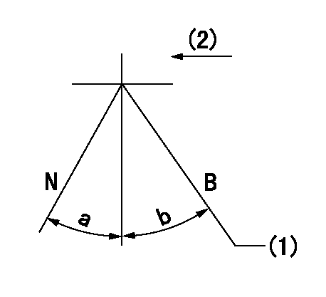
Stop lever angle
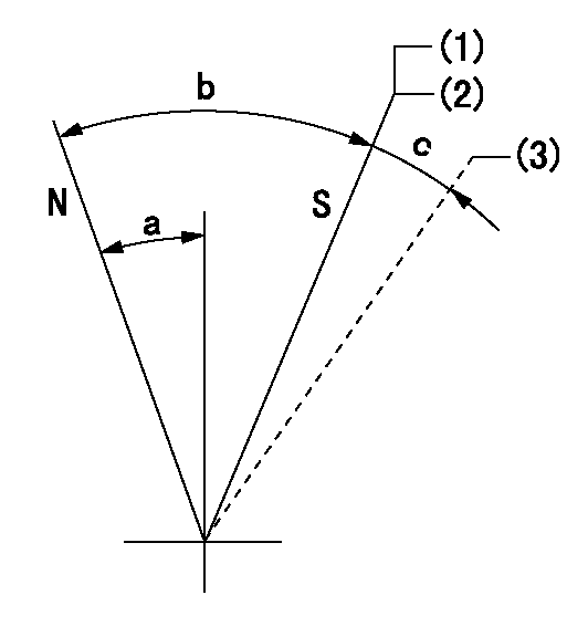
N:Pump normal
S:Stop the pump.
(1)Contacts inner stopper.
(2)Rack position aa or less, pump speed bb
(3)Contacts outer stopper.
----------
aa=4.2mm bb=0r/min
----------
a=27deg+-5deg b=53deg+-5deg c=(11deg)
----------
aa=4.2mm bb=0r/min
----------
a=27deg+-5deg b=53deg+-5deg c=(11deg)
0000001101
N:Normal
B:When boosted
(1)Rack position = aa (point E) at boost pressure = 0.
(2)Drive side
----------
aa=10.8+-0.1mm
----------
a=(15deg) b=(12deg)
----------
aa=10.8+-0.1mm
----------
a=(15deg) b=(12deg)
Timing setting

(1)Pump vertical direction
(2)Coupling's key groove position at No 1 cylinder's beginning of injection
(3)-
(4)-
----------
----------
a=(0deg)
----------
----------
a=(0deg)
Information:
3T1888 Alternator 24V 50A (Delco-Remy Number 117248)
3T1888 Alternator1. Remove the covers from the end of the alternator to get access to the voltage regulator.
Delco-Remy Regulator Adjustment
(1) Potentiometer adjustment screw. (2) Transistor pins.2. Remove the rubber from the potentiometer so that the small screw can be seen.3. Connect a voltmeter across the batteries to measure the regulation of the voltage. The batteries must have a good charge for this measurement.4. Operate the alternator at medium speed for 30 seconds and take a measurement of the voltage. The voltage must be 27.5 1.0 volts. Turn the small screw counterclockwise to get less voltage output and clockwise to get more voltage output.5. After adjustment has been made, put a think layer of 3S6252 Silicone Rubber Sealant on the adjustment screw and install the covers. Make sure the location of the wires to the voltage regulator is not over the transistor pins. The transistor pins could make holes in the insulation for the wires and cause a short circuit.7N9720 Alternator 24V 35A (Bosch Number 0-122-469-001); 9G9538 Alternator 24V 50A (Bosch Number 0-122-469-002)
7N9720 AlternatorThe solid state regulator used with the Bosch Alternator is totally enclosed and non-adjustable. If the rate of charge is not correct a replacement of the regulator is necessary.9G4574 24V 35A (Nippondenso Number 100211-0860); 6T7223 24V 50A (Nippondenso Number 100211-0890)
9G4574 AlternatorNo adjustment can be made to change the rate of charge on the alternator regulator. If rate of charge is not correct, a replacement of the regulator is necessary.Starting System
Use the multimeter in the DCV range to find starting system components which do not function.Move the start control switch to activate the starter solenoid. Starter solenoid operation can be heard as the pinion of the starter motor is engaged with the ring gear on the engine flywheel.If the solenoid for the starter motor will not operate, it is possible that the current from the battery did not get to the solenoid. Fasten one lead of the multimeter to the connection (terminal) for the battery cable on the solenoid. Put the other lead to a good ground. A zero reading is an indication that there is a broken circuit from the battery. More testing is necessary when there is a voltage reading on the multimeter.The solenoid operation also closes the electric circuit to the motor. Connect one lead of the multimeter to the solenoid connection (terminal) that is fastened to the motor. Put the other lead to a good ground. Activate the starter solenoid and look at the multimeter. A reading of battery voltage shows the problem is in the motor. The motor must be removed for further testing. A zero reading on the multimeter shows that the solenoid contacts do not close. This is an indication of the need for repair to the solenoid or an adjustment to be made to the starter pinion clearance.Make a test with one multimeter lead fastened to the connection (terminal) for the small wire at the solenoid and the other lead to the