Information injection-pump assembly
BOSCH
9 400 610 912
9400610912
ZEXEL
106673-3000
1066733000
HINO
220204900A
220204900a
Rating:
Service parts 106673-3000 INJECTION-PUMP ASSEMBLY:
1.
_
7.
COUPLING PLATE
8.
_
9.
_
11.
Nozzle and Holder
23600-1860D
12.
Open Pre:MPa(Kqf/cm2)
21.6{220}

15.
NOZZLE SET
Include in #1:
106673-3000
as INJECTION-PUMP ASSEMBLY
Cross reference number
BOSCH
9 400 610 912
9400610912
ZEXEL
106673-3000
1066733000
HINO
220204900A
220204900a
Zexel num
Bosch num
Firm num
Name
106673-3000
9 400 610 912
220204900A HINO
INJECTION-PUMP ASSEMBLY
K13D-T K
K13D-T K
Calibration Data:
Adjustment conditions
Test oil
1404 Test oil ISO4113 or {SAEJ967d}
1404 Test oil ISO4113 or {SAEJ967d}
Test oil temperature
degC
40
40
45
Nozzle and nozzle holder
105780-8140
Bosch type code
EF8511/9A
Nozzle
105780-0000
Bosch type code
DN12SD12T
Nozzle holder
105780-2080
Bosch type code
EF8511/9
Opening pressure
MPa
17.2
Opening pressure
kgf/cm2
175
Injection pipe
Outer diameter - inner diameter - length (mm) mm 8-3-600
Outer diameter - inner diameter - length (mm) mm 8-3-600
Overflow valve
134424-0920
Overflow valve opening pressure
kPa
162
147
177
Overflow valve opening pressure
kgf/cm2
1.65
1.5
1.8
Tester oil delivery pressure
kPa
157
157
157
Tester oil delivery pressure
kgf/cm2
1.6
1.6
1.6
Direction of rotation (viewed from drive side)
Left L
Left L
Injection timing adjustment
Direction of rotation (viewed from drive side)
Left L
Left L
Injection order
1-4-2-6-
3-5
Pre-stroke
mm
3.3
3.2
3.3
Beginning of injection position
Drive side NO.1
Drive side NO.1
Difference between angles 1
Cal 1-4 deg. 60 59.5 60.5
Cal 1-4 deg. 60 59.5 60.5
Difference between angles 2
Cyl.1-2 deg. 120 119.5 120.5
Cyl.1-2 deg. 120 119.5 120.5
Difference between angles 3
Cal 1-6 deg. 180 179.5 180.5
Cal 1-6 deg. 180 179.5 180.5
Difference between angles 4
Cal 1-3 deg. 240 239.5 240.5
Cal 1-3 deg. 240 239.5 240.5
Difference between angles 5
Cal 1-5 deg. 300 299.5 300.5
Cal 1-5 deg. 300 299.5 300.5
Injection quantity adjustment
Adjusting point
A
Rack position
8.8
Pump speed
r/min
950
950
950
Average injection quantity
mm3/st.
151
148
154
Max. variation between cylinders
%
0
-4
4
Basic
*
Fixing the lever
*
Injection quantity adjustment_02
Adjusting point
C
Rack position
6.7+-0.5
Pump speed
r/min
655
655
655
Average injection quantity
mm3/st.
61
59
63
Max. variation between cylinders
%
0
-15
15
Fixing the rack
*
Injection quantity adjustment_03
Adjusting point
D
Rack position
-
Pump speed
r/min
100
100
100
Average injection quantity
mm3/st.
140
140
150
Fixing the lever
*
Rack limit
*
Timer adjustment
Pump speed
r/min
800--
Advance angle
deg.
0
0
0
Remarks
Start
Start
Timer adjustment_02
Pump speed
r/min
750
Advance angle
deg.
0.5
Timer adjustment_03
Pump speed
r/min
950
Advance angle
deg.
1.5
1
2
Remarks
Finish
Finish
Test data Ex:
Governor adjustment
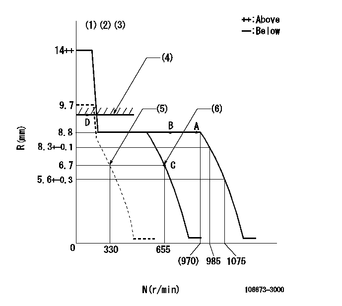
N:Pump speed
R:Rack position (mm)
(1)Target notch: K
(2)Tolerance for racks not indicated: +-0.05mm.
(3)Idle spring not operating.
(4)RACK LIMIT
(5)Set idle sub-spring
(6)Main spring setting
----------
K=12
----------
----------
K=12
----------
Speed control lever angle

F:Full speed
I:Idle
(1)Stopper bolt setting
----------
----------
a=4deg+-5deg b=12deg+-5deg
----------
----------
a=4deg+-5deg b=12deg+-5deg
Stop lever angle
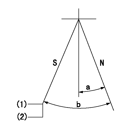
N:Pump normal
S:Stop the pump.
(1)Rack position aa or less, pump speed bb
(2)Normal stop
----------
aa=6.2mm bb=0r/min
----------
a=27deg+-5deg b=53deg+-5deg
----------
aa=6.2mm bb=0r/min
----------
a=27deg+-5deg b=53deg+-5deg
Timing setting

(1)Pump vertical direction
(2)Coupling's key groove position at No 1 cylinder's beginning of injection
(3)-
(4)-
----------
----------
a=(2deg)
----------
----------
a=(2deg)
Information:
(1) Thickness of spacer plate ... 9.970 0.025 mm (.3925 .0010 in) Thickness of spacer plate gasket ... 0.208 0.025 mm (.0082 .0010 in) For height of liner over top of spacer plate make reference to Cylinder Liner Projection.(2) Camshaft bearing bore (installed) ... 58.80 0.06 mm (2.315 .002 in) Bore in block for camshaft bearings ... 65.100 0.025 mm (2.5630 .0010 in)(3) Bore in block for main bearings (standard size) ... 96.926 0.013 mm (3.8160 .0005 in) Bore in block for main bearings 0.51 mm (.020 in) oversize ... 97.436 0.013 mm (3.8361 .0005 in)(4) Dimension from center of main bearing bore to top of cylinder block (new) ... 383.515 0.165 mm (15.099 .0064 in)(5) Dimension from center of main bearing bore to bottom of cylinder block (new) ... 153.99 0.10 mm (6.063 .004 in)(6) Torque for bolts holding bearing caps for main bearings: a. Put 2P2506 Thread Lubricant on threads and washer face.b. Tighten all bolts to ... 41 4 N m (30 3 lb ft)c. Put a mark on each bolt and cap.d. Tighten all bolts from mark ... 90 5° Install bearing caps with the part number toward the front of the engine. Be sure that the mark (number) on the bearing cap next to the bolt hole is in agreement with the mark in the cylinder block.(7) Clearance between main bearing cap and cylinder block ... 0.033 mm (.0013 in) tight to ... 0.043 mm (.0017 in) loose Main bearing cap width ... 165.095 0.020 mm (6.4998 .0008 in)Width of cylinder block for main bearing cap ... 165.100 0.018 mm (6.5000 .0007 in) (8) Piston cooling orifice.
There are holes in the bores for the main bearings, between the cylinders for piston cooling orifices. These holes must have orifices (8) installed.
(9) Distance two dowels extend from the surface of the cylinder block ... 19.8 0.5 mm (.78 .02 in)(10) Distance hollow dowel extends from the surface of the cylinder block ... 16.0 0.5 mm (.63 .02 in)(11) Depth to install two dowels below the surface of the cylinder block (apply loctite #11358) ... 1.0 0.5 mm (.04 .02 in)(12) Distance dowels extend from the front face of the cylinder block ... 22.4 0.5 mm (.88 .02 in)(13) Distance stud extends from the front face of the cylinder block ... 15.7 0.5 mm (.62 .02 in)(14) Distance two dowels extend from the rear face of the cylinder block ... 12.7 0.5 mm (.50 .02 in)
Have questions with 106673-3000?
Group cross 106673-3000 ZEXEL
Hino
106673-3000
9 400 610 912
220204900A
INJECTION-PUMP ASSEMBLY
K13D-T
K13D-T