Information injection-pump assembly
BOSCH
F 01G 09U 08P
f01g09u08p
ZEXEL
106673-2890
1066732890

Rating:
Service parts 106673-2890 INJECTION-PUMP ASSEMBLY:
1.
_
7.
COUPLING PLATE
8.
_
9.
_
11.
Nozzle and Holder
ME056804
12.
Open Pre:MPa(Kqf/cm2)
17.7{180}/24.5{250}

15.
NOZZLE SET
Include in #1:
106673-2890
as INJECTION-PUMP ASSEMBLY
Cross reference number
BOSCH
F 01G 09U 08P
f01g09u08p
ZEXEL
106673-2890
1066732890
Zexel num
Bosch num
Firm num
Name
Calibration Data:
Adjustment conditions
Test oil
1404 Test oil ISO4113 or {SAEJ967d}
1404 Test oil ISO4113 or {SAEJ967d}
Test oil temperature
degC
40
40
45
Nozzle and nozzle holder
105780-8140
Bosch type code
EF8511/9A
Nozzle
105780-0000
Bosch type code
DN12SD12T
Nozzle holder
105780-2080
Bosch type code
EF8511/9
Opening pressure
MPa
17.2
Opening pressure
kgf/cm2
175
Injection pipe
Outer diameter - inner diameter - length (mm) mm 8-3-600
Outer diameter - inner diameter - length (mm) mm 8-3-600
Overflow valve
131424-4620
Overflow valve opening pressure
kPa
255
221
289
Overflow valve opening pressure
kgf/cm2
2.6
2.25
2.95
Tester oil delivery pressure
kPa
157
157
157
Tester oil delivery pressure
kgf/cm2
1.6
1.6
1.6
Direction of rotation (viewed from drive side)
Right R
Right R
Injection timing adjustment
Direction of rotation (viewed from drive side)
Right R
Right R
Injection order
1-5-3-6-
2-4
Pre-stroke
mm
4.8
4.75
4.85
Beginning of injection position
Governor side NO.1
Governor side NO.1
Difference between angles 1
Cal 1-5 deg. 60 59.5 60.5
Cal 1-5 deg. 60 59.5 60.5
Difference between angles 2
Cal 1-3 deg. 120 119.5 120.5
Cal 1-3 deg. 120 119.5 120.5
Difference between angles 3
Cal 1-6 deg. 180 179.5 180.5
Cal 1-6 deg. 180 179.5 180.5
Difference between angles 4
Cyl.1-2 deg. 240 239.5 240.5
Cyl.1-2 deg. 240 239.5 240.5
Difference between angles 5
Cal 1-4 deg. 300 299.5 300.5
Cal 1-4 deg. 300 299.5 300.5
Injection quantity adjustment
Adjusting point
-
Rack position
10
Pump speed
r/min
700
700
700
Each cylinder's injection qty
mm3/st.
155
151.1
158.9
Basic
*
Fixing the rack
*
Standard for adjustment of the maximum variation between cylinders
*
Injection quantity adjustment_02
Adjusting point
F
Rack position
5+-0.5
Pump speed
r/min
500
500
500
Each cylinder's injection qty
mm3/st.
16.5
14
19
Fixing the rack
*
Standard for adjustment of the maximum variation between cylinders
*
Injection quantity adjustment_03
Adjusting point
A
Rack position
R1(10)
Pump speed
r/min
700
700
700
Average injection quantity
mm3/st.
155
154
156
Basic
*
Fixing the lever
*
Boost pressure
kPa
35.3
35.3
Boost pressure
mmHg
265
265
Injection quantity adjustment_04
Adjusting point
B
Rack position
R1(10)
Pump speed
r/min
1100
1100
1100
Average injection quantity
mm3/st.
165
161.8
168.2
Difference in delivery
mm3/st.
6.4
6.4
6.4
Fixing the lever
*
Boost pressure
kPa
35.3
35.3
Boost pressure
mmHg
265
265
Injection quantity adjustment_05
Adjusting point
C
Rack position
5.7+-0.5
Pump speed
r/min
225
225
225
Each cylinder's injection qty
mm3/st.
16.5
14
19
Fixing the rack
*
Boost pressure
kPa
0
0
0
Boost pressure
mmHg
0
0
0
Remarks
(check)
(check)
Injection quantity adjustment_06
Adjusting point
E
Rack position
-
Pump speed
r/min
100
100
100
Average injection quantity
mm3/st.
105
85
125
Fixing the lever
*
Boost pressure
kPa
0
0
0
Boost pressure
mmHg
0
0
0
Boost compensator adjustment
Pump speed
r/min
600
600
600
Rack position
R2(R1-1)
Boost pressure
kPa
10.7
10.7
10.7
Boost pressure
mmHg
80
80
80
Boost compensator adjustment_02
Pump speed
r/min
600
600
600
Rack position
9.1
Boost pressure
kPa
15.3
8.6
22
Boost pressure
mmHg
115
65
165
Boost compensator adjustment_03
Pump speed
r/min
600
600
600
Rack position
9.6
Boost pressure
kPa
17.3
16
18.6
Boost pressure
mmHg
130
120
140
Boost compensator adjustment_04
Pump speed
r/min
600
600
600
Rack position
R1(10)
Boost pressure
kPa
22
22
22
Boost pressure
mmHg
165
165
165
Timer adjustment
Pump speed
r/min
900--
Advance angle
deg.
0
0
0
Remarks
Start
Start
Timer adjustment_02
Pump speed
r/min
850
Advance angle
deg.
0.5
Timer adjustment_03
Pump speed
r/min
1100
Advance angle
deg.
1.5
1
2
Remarks
Finish
Finish
Test data Ex:
Governor adjustment
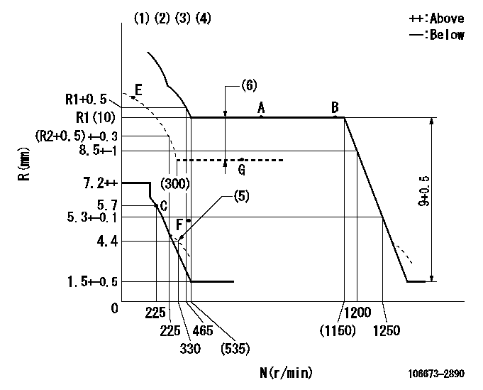
N:Pump speed
R:Rack position (mm)
(1)Lever ratio: RT
(2)Target shim dimension: TH
(3)Tolerance for racks not indicated: +-0.05mm.
(4)Boost compensator cancel stroke: BSL
(5)Damper spring setting
(6)Boost compensator stroke: BCL
----------
RT=1 TH=2.3mm BSL=2.2mm BCL=1+-0.1mm
----------
----------
RT=1 TH=2.3mm BSL=2.2mm BCL=1+-0.1mm
----------
Speed control lever angle

F:Full speed
----------
----------
a=15deg+-5deg
----------
----------
a=15deg+-5deg
0000000901
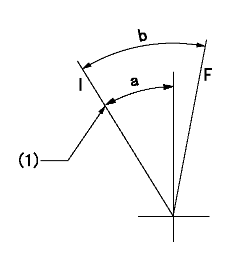
F:Full load
I:Idle
(1)Stopper bolt setting
----------
----------
a=24deg+-5deg b=31.5deg+-3deg
----------
----------
a=24deg+-5deg b=31.5deg+-3deg
Stop lever angle
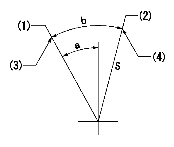
S:Stop the pump.
(1)Free (at delivery)
(2)Rack position = aa
(3)Stopper bolt setting
(4)Stopper bolt setting
----------
aa=4.1-0.5mm
----------
a=25.5deg+-5deg b=37deg+7deg-5deg
----------
aa=4.1-0.5mm
----------
a=25.5deg+-5deg b=37deg+7deg-5deg
0000001501 MICRO SWITCH
Adjustment of the micro-switch
Adjust the bolt to obtain the following lever position when the micro-switch is ON.
(1)Speed N1
(2)Rack position Ra
----------
N1=325r/min Ra=5.4+-0.1mm
----------
----------
N1=325r/min Ra=5.4+-0.1mm
----------
Timing setting

(1)Pump vertical direction
(2)Coupling's key groove position at No 1 cylinder's beginning of injection
(3)B.T.D.C.: aa
(4)-
----------
aa=9deg
----------
a=(7deg)
----------
aa=9deg
----------
a=(7deg)
Information:
Always use a wrench to hold the hex fitting on top of the master nozzle, when assembling or disassembling lines. If a wrench is not used, the master nozzle and manifold it is installed into may be damaged.
Check fuel line for "Close-in" Do NOT use fuel lines with an ID (inside diameter) LESS than 1.191 mm (0.0469 in). The fuel line ID can be checked using a 1.2 mm (.047 in) drill.If the drill bit can NOT be inserted into the fuel line high pressure hole, either drill out the line using a 1.6 mm (.063 in) drill or replace the fuel line with a new line. Use the same length and internal diameter lines each time the reference pump is tested.
If the fuel lines are not completely and thoroughly cleaned out after the drilling procedure, metal particles or foreign debris in the line will damage the master nozzles and contaminate the calibration fluid in the test stand.
After the hole has been drilled to the correct size, clean the line with solvent and remove any metal particles. Blow compressed air through the lines, after cleaning, to remove any solvent.
When using pressure air, wear a protective face shield and protective clothing. The maximum air pressure at the nozzle must be less than 205 kPa (30 psi) for cleaning purposes.
9. Identify fuel lines and nozzles in the same order as the reference pump plunger and barrels (1-6 or 1-12) and use the same lines and nozzles each time the reference pump is run on the test bench.10. Select two test points (speeds and shot settings) that will cover the delivery range realized in a dealer's shop.Always set up the test points using only the pump rack zero pin. Do not set the rack full load or idle stops.11. The test stand and reference pump should be run for ten minutes.Make sure test stand pressures and temperatures are within published specifications and that they are stable.12. Set the first test point.Take five samples (draws) and record the individual pump and barrel deliveries for each sample (draw).13. Examine pump and barrel sample data:* Are the samples consistent?The MAXIMUM allowable difference between the HIGH and LOW delivery pump and barrel in the reference pump should be three cc's.If there is NOT a three cc difference, swap pump and barrels in the pump housing (or check master nozzles for damage) and re-test UNTIL the maximum HIGH to LOW