Information injection-pump assembly
BOSCH
9 400 617 263
9400617263
ZEXEL
106673-2750
1066732750
MITSUBISHI
ME2E6075
me2e6075
Rating:
Cross reference number
BOSCH
9 400 617 263
9400617263
ZEXEL
106673-2750
1066732750
MITSUBISHI
ME2E6075
me2e6075
Zexel num
Bosch num
Firm num
Name
Calibration Data:
Adjustment conditions
Test oil
1404 Test oil ISO4113 or {SAEJ967d}
1404 Test oil ISO4113 or {SAEJ967d}
Test oil temperature
degC
40
40
45
Nozzle and nozzle holder
105780-8140
Bosch type code
EF8511/9A
Nozzle
105780-0000
Bosch type code
DN12SD12T
Nozzle holder
105780-2080
Bosch type code
EF8511/9
Opening pressure
MPa
17.2
Opening pressure
kgf/cm2
175
Injection pipe
Outer diameter - inner diameter - length (mm) mm 8-3-600
Outer diameter - inner diameter - length (mm) mm 8-3-600
Overflow valve
131424-4620
Overflow valve opening pressure
kPa
255
221
289
Overflow valve opening pressure
kgf/cm2
2.6
2.25
2.95
Tester oil delivery pressure
kPa
157
157
157
Tester oil delivery pressure
kgf/cm2
1.6
1.6
1.6
Direction of rotation (viewed from drive side)
Right R
Right R
Injection timing adjustment
Direction of rotation (viewed from drive side)
Right R
Right R
Injection order
1-5-3-6-
2-4
Pre-stroke
mm
4.8
4.75
4.85
Beginning of injection position
Governor side NO.1
Governor side NO.1
Difference between angles 1
Cal 1-5 deg. 60 59.5 60.5
Cal 1-5 deg. 60 59.5 60.5
Difference between angles 2
Cal 1-3 deg. 120 119.5 120.5
Cal 1-3 deg. 120 119.5 120.5
Difference between angles 3
Cal 1-6 deg. 180 179.5 180.5
Cal 1-6 deg. 180 179.5 180.5
Difference between angles 4
Cyl.1-2 deg. 240 239.5 240.5
Cyl.1-2 deg. 240 239.5 240.5
Difference between angles 5
Cal 1-4 deg. 300 299.5 300.5
Cal 1-4 deg. 300 299.5 300.5
Injection quantity adjustment
Adjusting point
A
Rack position
12.1
Pump speed
r/min
800
800
800
Average injection quantity
mm3/st.
142.7
139.7
145.7
Max. variation between cylinders
%
0
-3
3
Basic
*
Fixing the lever
*
Boost pressure
kPa
62.7
62.7
Boost pressure
mmHg
470
470
Injection quantity adjustment_02
Adjusting point
B
Rack position
6.1+-0.5
Pump speed
r/min
275
275
275
Average injection quantity
mm3/st.
13.8
11.2
16.4
Max. variation between cylinders
%
0
-15
15
Fixing the rack
*
Boost pressure
kPa
0
0
0
Boost pressure
mmHg
0
0
0
Injection quantity adjustment_03
Adjusting point
D
Rack position
-
Pump speed
r/min
100
100
100
Average injection quantity
mm3/st.
121
101
141
Fixing the lever
*
Boost pressure
kPa
0
0
0
Boost pressure
mmHg
0
0
0
Rack limit
*
Boost compensator adjustment
Pump speed
r/min
600
600
600
Rack position
10.7
Boost pressure
kPa
13.3
12
14.6
Boost pressure
mmHg
100
90
110
Boost compensator adjustment_02
Pump speed
r/min
600
600
600
Rack position
12.1
Boost pressure
kPa
49.3
42.6
56
Boost pressure
mmHg
370
320
420
Timer adjustment
Pump speed
r/min
950--
Advance angle
deg.
0
0
0
Remarks
Start
Start
Timer adjustment_02
Pump speed
r/min
900
Advance angle
deg.
0.5
Timer adjustment_03
Pump speed
r/min
1100
Advance angle
deg.
1
0.5
1.5
Remarks
Finish
Finish
Test data Ex:
Governor adjustment
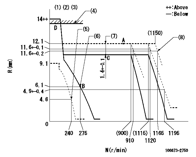
N:Pump speed
R:Rack position (mm)
(1)Target notch: K
(2)Tolerance for racks not indicated: +-0.05mm.
(3)The torque control spring does not operate.
(4)RACK LIMIT
(5)Set idle sub-spring
(6)Main spring setting
(7)Boost compensator stroke
(8)Set at delivery
----------
K=6
----------
----------
K=6
----------
Speed control lever angle
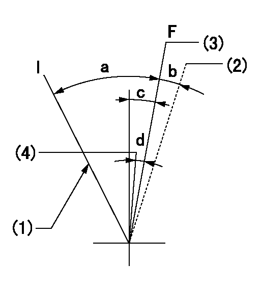
F:Full speed
I:Idle
(1)Stopper bolt setting
(2)At delivery
(3)Set the pump speed at aa
(4)Set the pump speed at bb.
----------
aa=1120r/min bb=910r/min
----------
a=29deg+-5deg b=(2deg) c=8deg+-5deg d=7deg+-5deg
----------
aa=1120r/min bb=910r/min
----------
a=29deg+-5deg b=(2deg) c=8deg+-5deg d=7deg+-5deg
Stop lever angle
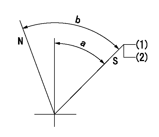
N:Pump normal
S:Stop the pump.
(1)Pump speed aa and rack position bb (to be sealed at delivery)
(2)Stopper bolt setting
----------
aa=0r/min bb=1-0.2mm
----------
a=50deg+-5deg b=70deg+-5deg
----------
aa=0r/min bb=1-0.2mm
----------
a=50deg+-5deg b=70deg+-5deg
0000001501 RACK SENSOR

(VR) measurement voltage
(I) Part number of the control unit
(G) Apply red paint.
(H): End surface of the pump
1. Rack sensor adjustment (-0620)
(1)Fix the speed control lever at the full position
(2)Set the speed to N1 r/min.
(If the boost compensator is provided, apply boost pressure.)
(3)Adjust the bobbin (A) so that the rack sensor's output voltage is VR+-0.01.
(4)At that time, rack position must be Ra.
(5)Apply G at two places.
Connecting part between the joint (B) and the nut (F)
Connecting part between the joint (B) and the end surface of the pump (H)
----------
N1=800r/min Ra=12.1mm
----------
----------
N1=800r/min Ra=12.1mm
----------
Timing setting

(1)Pump vertical direction
(2)Coupling's key groove position at No 1 cylinder's beginning of injection
(3)-
(4)-
----------
----------
a=(7deg)
----------
----------
a=(7deg)
Information:
(1) Crossbar (from 8B7548 Puller).(2) Spacer plate.(3) S1589 Bolt with two 1S379 Washers.(4) 1D4595 Bolt.(5) 3H465 Plate.(6) 1P2403 Dial Indicator.(7) 1P2394 Adapter Plate.(8) 1P2402 Gauge Body.Make reference to Cylinder Liner Projection in Testing and Adjusting for the complete procedure.1. Install gasket and spacer plate (2) with bolts (3) and two 1S379 Washers. Tighten bolts (3) evenly in four steps: 1st step ... 14 N m (10 lb ft)2nd step ... 35 N m (25 lb ft)3rd step ... 70 N m (50 lb ft)4th step ... 95 N m (70 lb ft)2. Install tools as shown. Tighten bolts (4) evenly in four steps: 1st step ... 7 N m (5 lb ft)2nd step ... 20 N m (15 lb ft)3rd step ... 35 N m (25 lb ft)4th step ... 70 N m (50 lb ft)3. Measure cylinder liner projection with dial indicator (6) in 1P2402 Gauge Body (8) as shown. Measure at four places around each cylinder liner near the clamped area. Cylinder liner projection measurements for any cylinder liner must be ... 0.033 to 0.175 mm (.0013 to .0069 in)Maximum permissible difference between all four measurements ... 0.05 mm (.002 in)Maximum permissible difference between average projection of any two cylinder liners next to each other ... 0.05 mm (.002 in)Maximum permissible difference between average projection of all cylinder liners under one cylinder head ... 0.08 mm (.003 in) If liner projection is not correct, turn the liner to a new position within the bore. If projection can not be corrected this way, move the liner to a different bore. If the projection can not be corrected this way, make reference to Special Instruction, Form No. FMO55228 for complete instructions on the use of 8S3140 Counterboring Tool Arrangement. 4. Minimum permissible depth to machine counterbore to adjust cylinder liner projection ... 0.76 mm (.030 in) Maximum permissible depth to machine counterbore to adjust cylinder liner projection ... 1.14 mm (.045 in) install a 0.76 mm (.030 in) shim plus any added shims necessary to get the correct cylinder liner projection. Be sure that the 0.76 mm (.030 in) shim is directly under the cylinder liner flange.