Information injection-pump assembly
BOSCH
F 019 Z10 534
f019z10534
ZEXEL
106673-2520
1066732520

Rating:
Service parts 106673-2520 INJECTION-PUMP ASSEMBLY:
1.
_
7.
COUPLING PLATE
8.
_
9.
_
11.
Nozzle and Holder
ME059622
12.
Open Pre:MPa(Kqf/cm2)
21.6(220)
15.
NOZZLE SET
Include in #1:
106673-2520
as INJECTION-PUMP ASSEMBLY
Cross reference number
BOSCH
F 019 Z10 534
f019z10534
ZEXEL
106673-2520
1066732520
Zexel num
Bosch num
Firm num
Name
Calibration Data:
Adjustment conditions
Test oil
1404 Test oil ISO4113 or {SAEJ967d}
1404 Test oil ISO4113 or {SAEJ967d}
Test oil temperature
degC
40
40
45
Nozzle and nozzle holder
105780-8140
Bosch type code
EF8511/9A
Nozzle
105780-0000
Bosch type code
DN12SD12T
Nozzle holder
105780-2080
Bosch type code
EF8511/9
Opening pressure
MPa
17.2
Opening pressure
kgf/cm2
175
Injection pipe
Outer diameter - inner diameter - length (mm) mm 8-3-600
Outer diameter - inner diameter - length (mm) mm 8-3-600
Overflow valve
131424-4620
Overflow valve opening pressure
kPa
255
221
289
Overflow valve opening pressure
kgf/cm2
2.6
2.25
2.95
Tester oil delivery pressure
kPa
157
157
157
Tester oil delivery pressure
kgf/cm2
1.6
1.6
1.6
Direction of rotation (viewed from drive side)
Right R
Right R
Injection timing adjustment
Direction of rotation (viewed from drive side)
Right R
Right R
Injection order
1-5-3-6-
2-4
Pre-stroke
mm
4.8
4.75
4.85
Beginning of injection position
Governor side NO.1
Governor side NO.1
Difference between angles 1
Cal 1-5 deg. 60 59.5 60.5
Cal 1-5 deg. 60 59.5 60.5
Difference between angles 2
Cal 1-3 deg. 120 119.5 120.5
Cal 1-3 deg. 120 119.5 120.5
Difference between angles 3
Cal 1-6 deg. 180 179.5 180.5
Cal 1-6 deg. 180 179.5 180.5
Difference between angles 4
Cyl.1-2 deg. 240 239.5 240.5
Cyl.1-2 deg. 240 239.5 240.5
Difference between angles 5
Cal 1-4 deg. 300 299.5 300.5
Cal 1-4 deg. 300 299.5 300.5
Injection quantity adjustment
Adjusting point
A
Rack position
12
Pump speed
r/min
1050
1050
1050
Average injection quantity
mm3/st.
137.2
134.2
140.2
Max. variation between cylinders
%
0
-3
3
Basic
*
Fixing the lever
*
Injection quantity adjustment_02
Adjusting point
B
Rack position
5.8+-0.5
Pump speed
r/min
500
500
500
Average injection quantity
mm3/st.
15
12.4
17.6
Max. variation between cylinders
%
0
-15
15
Fixing the rack
*
Injection quantity adjustment_03
Adjusting point
C
Rack position
13.9+-0.
5
Pump speed
r/min
100
100
100
Average injection quantity
mm3/st.
133
113
153
Fixing the lever
*
Rack limit
*
Injection quantity adjustment_04
Adjusting point
D
Rack position
6.9+-0.5
Pump speed
r/min
225
225
225
Average injection quantity
mm3/st.
15
12.4
17.6
Fixing the rack
*
Remarks
(check)
(check)
Timer adjustment
Pump speed
r/min
1200
Advance angle
deg.
0.5
Timer adjustment_02
Pump speed
r/min
-
Advance angle
deg.
2
2
2
Remarks
Measure the actual speed, stop
Measure the actual speed, stop
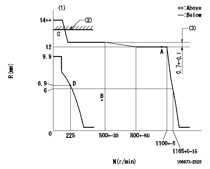
Test data Ex:
Governor adjustment

N:Pump speed
R:Rack position (mm)
(1)Target notch: K
(2)RACK LIMIT
(3)Rack difference between N = N1 and N = N2
----------
K=5 N1=1050r/min N2=450r/min
----------
----------
K=5 N1=1050r/min N2=450r/min
----------
Speed control lever angle

F:Full speed
I:Idle
(1)Stopper bolt setting
----------
----------
a=30deg+-5deg b=6deg+-5deg
----------
----------
a=30deg+-5deg b=6deg+-5deg
Stop lever angle

N:Pump normal
S:Stop the pump.
----------
----------
a=36.5deg+-5deg b=53deg+-5deg
----------
----------
a=36.5deg+-5deg b=53deg+-5deg
Timing setting

(1)Pump vertical direction
(2)Coupling's key groove position at No 1 cylinder's beginning of injection
(3)-
(4)-
----------
----------
a=(7deg)
----------
----------
a=(7deg)
Information:
The cylinder head is either water-cooled or air-cooled by fins in order to prevent overheating by the compression heat of the air compressor.The water-cooled type has coolant led from the oil cooler to cool cylinder head valves. Coolant is then returned to the rear end of the engine cylinder head.1.2 Pressure Governor
The pressure governor controls compressor operation to keep the air tank pressure within specified limits.To the high pressure valve of the diaphragm, the same air pressure as in the air tank acts always through the filter, thereby balancing with the adjusting spring force. When the pressure in the air tank increases to exceed that opening pressure of the high pressure valve, the air forces up the high pressure valve seat of the diaphragm. This causes increase of acting area so that the diaphragm moves up quickly to close the seat of the low pressure valve.When the low pressure valve is closed, air now flows through the valve body to force down the unloader valve of the air compressor, thereby stopping air supply to the air tank.As the air pressure in the air tank gradually drops, the diaphragm is forced down by the adjusting spring and the low pressure valve opens and the high pressure one closes. As a result, the air on the unloader side is exhausted through the exhaust hole and air supply to the air tank is resumed.2. Specifications
3. Service Standards
3.1 Service Standards Table
(1) Air Compressor (2) Pressure Governor 3.2 Tightening Torque Table
(1) Air compressor (2) Pressure governor 4. Special Tool
5. Service Procedure
5.1 Air Compressor
Removal and installation
The removal and installation procedures of the air compressor are same as those of the pump drive case. See Group 13 Fuel and Engine Control.Disassembly
Disassembly(1) Removal of suction valve holder Using special tool, Air Compressor Suction Valve Tool, remove the suction valve holder.(2) Removal of delivery valve holder (Air-cooled type only) Using special tool, Air Compressor Delivery Valve Tool, remove the delivery valve holder.(3) Removal of piston ring Using special tool, Piston Ring Tool, remove the piston ring.Inspection
Inspection(1) Piston to cylinder liner clearance Calculate the clearance and if it exceeds the limit, replace the piston or cylinder liner.(2) Piston ring to ring groove clearance Measure the clearance and if it exceeds the limit, replace the piston ring or piston. Measure over entire circumference of the piston.(3) Piston ring open end gap Fit the piston ring to a new cylinder liner or gauge and measure the open end gap. If the gap exceeds the limit, replace the ring. Push in the piston ring flat by the piston and measure.(4) Piston to piston pin clearance Calculate the clearance and if it exceeds the limit, replace the piston or piston pin.(5) Piston to connecting rod clearance Calculate the clearance and if it exceeds the limit, replace the piston pin or connecting rod.(6) Crankshaft pin to connecting rod bearing clearance Calculate the clearance and if it exceeds the limit, replace the bearing.(7) Connecting rod end play If the end play exceeds the limit,
