Information injection-pump assembly
BOSCH
9 400 617 242
9400617242
ZEXEL
106673-2510
1066732510
MITSUBISHI
ME056899
me056899
Rating:
Service parts 106673-2510 INJECTION-PUMP ASSEMBLY:
1.
_
7.
COUPLING PLATE
8.
_
9.
_
11.
Nozzle and Holder
ME056357
12.
Open Pre:MPa(Kqf/cm2)
17.7{180}/21.6{220}
15.
NOZZLE SET
Include in #1:
106673-2510
as INJECTION-PUMP ASSEMBLY
Cross reference number
BOSCH
9 400 617 242
9400617242
ZEXEL
106673-2510
1066732510
MITSUBISHI
ME056899
me056899
Zexel num
Bosch num
Firm num
Name
106673-2510
9 400 617 242
ME056899 MITSUBISHI
INJECTION-PUMP ASSEMBLY
6D22T2 K
6D22T2 K
Calibration Data:
Adjustment conditions
Test oil
1404 Test oil ISO4113 or {SAEJ967d}
1404 Test oil ISO4113 or {SAEJ967d}
Test oil temperature
degC
40
40
45
Nozzle and nozzle holder
105780-8140
Bosch type code
EF8511/9A
Nozzle
105780-0000
Bosch type code
DN12SD12T
Nozzle holder
105780-2080
Bosch type code
EF8511/9
Opening pressure
MPa
17.2
Opening pressure
kgf/cm2
175
Injection pipe
Outer diameter - inner diameter - length (mm) mm 8-3-600
Outer diameter - inner diameter - length (mm) mm 8-3-600
Overflow valve
131424-4620
Overflow valve opening pressure
kPa
255
221
289
Overflow valve opening pressure
kgf/cm2
2.6
2.25
2.95
Tester oil delivery pressure
kPa
157
157
157
Tester oil delivery pressure
kgf/cm2
1.6
1.6
1.6
Direction of rotation (viewed from drive side)
Right R
Right R
Injection timing adjustment
Direction of rotation (viewed from drive side)
Right R
Right R
Injection order
1-5-3-6-
2-4
Pre-stroke
mm
4.8
4.75
4.85
Beginning of injection position
Governor side NO.1
Governor side NO.1
Difference between angles 1
Cal 1-5 deg. 60 59.5 60.5
Cal 1-5 deg. 60 59.5 60.5
Difference between angles 2
Cal 1-3 deg. 120 119.5 120.5
Cal 1-3 deg. 120 119.5 120.5
Difference between angles 3
Cal 1-6 deg. 180 179.5 180.5
Cal 1-6 deg. 180 179.5 180.5
Difference between angles 4
Cyl.1-2 deg. 240 239.5 240.5
Cyl.1-2 deg. 240 239.5 240.5
Difference between angles 5
Cal 1-4 deg. 300 299.5 300.5
Cal 1-4 deg. 300 299.5 300.5
Injection quantity adjustment
Adjusting point
-
Rack position
9.4
Pump speed
r/min
700
700
700
Each cylinder's injection qty
mm3/st.
144
140.5
147.5
Basic
*
Fixing the rack
*
Standard for adjustment of the maximum variation between cylinders
*
Injection quantity adjustment_02
Adjusting point
F
Rack position
5+-0.5
Pump speed
r/min
500
500
500
Each cylinder's injection qty
mm3/st.
16.5
14
19
Fixing the rack
*
Standard for adjustment of the maximum variation between cylinders
*
Injection quantity adjustment_03
Adjusting point
A
Rack position
R1(9.4)
Pump speed
r/min
700
700
700
Average injection quantity
mm3/st.
144
143
145
Basic
*
Fixing the lever
*
Boost pressure
kPa
43.3
43.3
Boost pressure
mmHg
325
325
Injection quantity adjustment_04
Adjusting point
B
Rack position
R1(9.4)
Pump speed
r/min
1100
1100
1100
Average injection quantity
mm3/st.
152.8
149.6
156
Difference in delivery
mm3/st.
6.4
6.4
6.4
Fixing the lever
*
Boost pressure
kPa
43.3
43.3
Boost pressure
mmHg
325
325
Injection quantity adjustment_05
Adjusting point
D
Rack position
9.3
Pump speed
r/min
500
500
500
Average injection quantity
mm3/st.
139.5
135.5
143.5
Fixing the lever
*
Boost pressure
kPa
28
28
28
Boost pressure
mmHg
210
210
210
Injection quantity adjustment_06
Adjusting point
C
Rack position
5.7+-0.5
Pump speed
r/min
225
225
225
Each cylinder's injection qty
mm3/st.
16.5
14
19
Fixing the rack
*
Boost pressure
kPa
0
0
0
Boost pressure
mmHg
0
0
0
Remarks
(check)
(check)
Injection quantity adjustment_07
Adjusting point
E
Rack position
-
Pump speed
r/min
100
100
100
Average injection quantity
mm3/st.
125
105
145
Fixing the lever
*
Boost pressure
kPa
0
0
0
Boost pressure
mmHg
0
0
0
Boost compensator adjustment
Pump speed
r/min
600
600
600
Rack position
R2(R1-1.
5)
Boost pressure
kPa
3.3
3.3
3.3
Boost pressure
mmHg
25
25
25
Boost compensator adjustment_02
Pump speed
r/min
600
600
600
Rack position
8.55
Boost pressure
kPa
14.7
8
21.4
Boost pressure
mmHg
110
60
160
Boost compensator adjustment_03
Pump speed
r/min
600
600
600
Rack position
9.3
Boost pressure
kPa
28
26.7
29.3
Boost pressure
mmHg
210
200
220
Boost compensator adjustment_04
Pump speed
r/min
600
600
600
Rack position
R1(9.4)
Boost pressure
kPa
30
30
30
Boost pressure
mmHg
225
225
225
Timer adjustment
Pump speed
r/min
450--
Advance angle
deg.
0
0
0
Remarks
Start
Start
Timer adjustment_02
Pump speed
r/min
400
Advance angle
deg.
0.5
Timer adjustment_03
Pump speed
r/min
800
Advance angle
deg.
3
2.5
3.5
Remarks
Finish
Finish
Test data Ex:
Governor adjustment
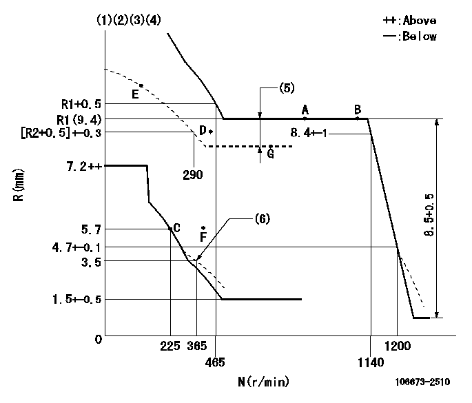
N:Pump speed
R:Rack position (mm)
(1)Lever ratio: RT
(2)Target shim dimension: TH
(3)Tolerance for racks not indicated: +-0.05mm.
(4)Boost compensator cancel stroke: BSL
(5)Boost compensator stroke: BCL
(6)Damper spring setting
----------
RT=1 TH=1.9mm BSL=2.2mm BCL=1.5+-0.1mm
----------
----------
RT=1 TH=1.9mm BSL=2.2mm BCL=1.5+-0.1mm
----------
Speed control lever angle
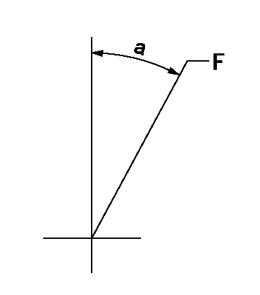
F:Full speed
----------
----------
a=(14deg)+-5deg
----------
----------
a=(14deg)+-5deg
0000000901
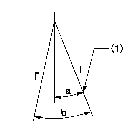
F:Full load
I:Idle
(1)Stopper bolt setting
----------
----------
a=28deg+-5deg b=29deg+-3deg
----------
----------
a=28deg+-5deg b=29deg+-3deg
Stop lever angle
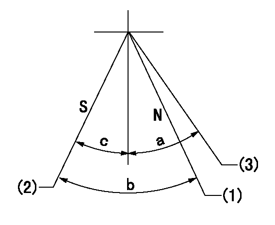
N:Engine manufacturer's normal use
S:Stop the pump.
(1)Rack position = aa
(2)Rack position = bb, set the stopper bolt.
(3)Free (at shipping)
----------
aa=13.3mm bb=4.1-0.5mm
----------
a=(38deg) b=26deg+-5deg c=0deg+7deg-5deg
----------
aa=13.3mm bb=4.1-0.5mm
----------
a=(38deg) b=26deg+-5deg c=0deg+7deg-5deg
0000001501 MICRO SWITCH
Adjustment of the micro-switch
Adjust the bolt to obtain the following lever position when the micro-switch is ON.
(1)Speed N1
(2)Rack position Ra
----------
N1=325r/min Ra=5.4+-0.1mm
----------
----------
N1=325r/min Ra=5.4+-0.1mm
----------
Timing setting

(1)Pump vertical direction
(2)Coupling's key groove position at No 1 cylinder's beginning of injection
(3)-
(4)-
----------
----------
a=(7deg)
----------
----------
a=(7deg)
Information:
3.1 Service Standards Table
3.2 Tightening torque table
4. Special Tool
5. Service Procedures
5.1 Removal and Installation
(1) Removal (a) When removing the pressure plate and lever assembly, fix the pressure plate using the special tools, Stopper Bolt and Washer. (C4 and C8 only) (b) Install the special tool, Clutch Alignment Arbor to prevent drop of the clutch disc and then remove the pressure plate and lever assembly.(2) Installation (a) Install the clutch disc using the special tool, Clutch Alignment Arbor. When installing the clutch disc, use care not to confuse the front and reverse sides. Install with the side bearing the part No. facing outside. (b) Install the pressure plate and lever assembly, aligning with the knock pins of the fly wheel. In the case of C4 and C8, install after fixing the pressure plate using special tools, Stopper Bolt and Washer. 1. Before installing the clutch, check and clean the flywheel. If faulty, correct or replace.2. When tightening the bolts, do so in diagonal order and uniformly.3. After installation, be sure to remove the Stopper Bolt and Washer. (C4 and C8 only)(c) Inspection of release lever plate height (at clutch disc replacement only) Using special tool, Clutch Release Lever Aligner, check the height of the clutch cover and release lever plate.If adjustment is necessary, adjust referring to 5.2.2 (3).(d) Adjustment after installation of bearing case. After installation, adjust the free travel (clearance between the release bearing and release lever). 1) Move the lever in the direction to engage the clutch. At a position where a click is heard in the clutch, turn the adjusting bolt A until it is blocked by the stopper, and lock it by turning down the bolt another two or three threads.2) From the position where the release bearing has touched the release lever, turn the adjusting screw B in the direction to disengage the clutch and check to see that the clutch is in disengaged position. Then lock the bolt. When making adjustment, lock in position the ratchet of the lever of the opposite side. 1) Loosen the control ling lock nut and from the position where the release bearing is in contact with the release lever, move back by B1 mm and lock in position (clutch lever setting position when clutch is engaged).2) In the direction to disengage the clutch, lock the air cylinder adjusting bolt at a position B2 mm from the position where the release bearing is in contact with the release lever.5.2 Clutch Proper
Disassembly and inspection
Disassembly and Inspection(1) Removal of clutch cover (a) Matchmark the clutch cover and pressure plate and using special tool, Clutch Installer, compress the pressure spring and remove support lever nut, strap bolt, etc.(b) Slowly loosen the handle of the Clutch Installer to remove the clutch cover.(2) Wear of facing Measure the depth from facing surface to rivet head. If the depth is smaller than the limit, replace the clutch disc assembly.(3) Runout of clutch disc Using a runout tester, measure the runout of the clutch
Have questions with 106673-2510?
Group cross 106673-2510 ZEXEL
Mitsubishi
106673-2510
9 400 617 242
ME056899
INJECTION-PUMP ASSEMBLY
6D22T2
6D22T2
