Information injection-pump assembly
BOSCH
9 400 617 193
9400617193
ZEXEL
106672-9932
1066729932
KOMATSU
6152711992
6152711992

Rating:
Cross reference number
BOSCH
9 400 617 193
9400617193
ZEXEL
106672-9932
1066729932
KOMATSU
6152711992
6152711992
Zexel num
Bosch num
Firm num
Name
106672-9932
9 400 617 193
6152711992 KOMATSU
INJECTION-PUMP ASSEMBLY
SA6D125 K
SA6D125 K
Calibration Data:
Adjustment conditions
Test oil
1404 Test oil ISO4113 or {SAEJ967d}
1404 Test oil ISO4113 or {SAEJ967d}
Test oil temperature
degC
40
40
45
Nozzle and nozzle holder
105780-8140
Bosch type code
EF8511/9A
Nozzle
105780-0000
Bosch type code
DN12SD12T
Nozzle holder
105780-2080
Bosch type code
EF8511/9
Opening pressure
MPa
17.2
Opening pressure
kgf/cm2
175
Injection pipe
Outer diameter - inner diameter - length (mm) mm 8-3-600
Outer diameter - inner diameter - length (mm) mm 8-3-600
Overflow valve
131425-2120
Overflow valve opening pressure
kPa
157
157
157
Overflow valve opening pressure
kgf/cm2
1.6
1.6
1.6
Tester oil delivery pressure
kPa
157
157
157
Tester oil delivery pressure
kgf/cm2
1.6
1.6
1.6
Direction of rotation (viewed from drive side)
Left L
Left L
Injection timing adjustment
Direction of rotation (viewed from drive side)
Left L
Left L
Injection order
1-5-3-6-
2-4
Pre-stroke
mm
3.8
3.75
3.85
Beginning of injection position
Drive side NO.1
Drive side NO.1
Difference between angles 1
Cal 1-5 deg. 60 59.5 60.5
Cal 1-5 deg. 60 59.5 60.5
Difference between angles 2
Cal 1-3 deg. 120 119.5 120.5
Cal 1-3 deg. 120 119.5 120.5
Difference between angles 3
Cal 1-6 deg. 180 179.5 180.5
Cal 1-6 deg. 180 179.5 180.5
Difference between angles 4
Cyl.1-2 deg. 240 239.5 240.5
Cyl.1-2 deg. 240 239.5 240.5
Difference between angles 5
Cal 1-4 deg. 300 299.5 300.5
Cal 1-4 deg. 300 299.5 300.5
Injection quantity adjustment
Adjusting point
A
Rack position
11
Pump speed
r/min
900
900
900
Average injection quantity
mm3/st.
183.5
181.5
185.5
Max. variation between cylinders
%
0
-3
3
Basic
*
Fixing the rack
*
Injection quantity adjustment_02
Adjusting point
B
Rack position
5.7+-0.5
Pump speed
r/min
325
325
325
Average injection quantity
mm3/st.
13
11.5
14.5
Max. variation between cylinders
%
0
-15
15
Fixing the rack
*
Test data Ex:
Governor adjustment
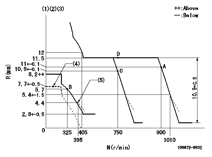
N:Pump speed
R:Rack position (mm)
(1)Lever ratio: RT
(2)Target shim dimension: TH
(3)Tolerance for racks not indicated: +-0.05mm.
(4)Load lever at stop
(5)Damper spring setting
----------
RT=1 TH=2.4mm
----------
----------
RT=1 TH=2.4mm
----------
Speed control lever angle
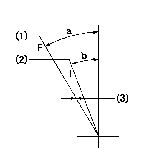
F:Full speed
I:Idle
(1)Set the pump speed at aa
(2)Set the pump speed at bb.
(3)Set the stopper bolt (fixed at full-load position at delivery.)
----------
aa=900r/min bb=750r/min
----------
a=11deg+-5deg b=9.5deg+-5deg
----------
aa=900r/min bb=750r/min
----------
a=11deg+-5deg b=9.5deg+-5deg
0000000901
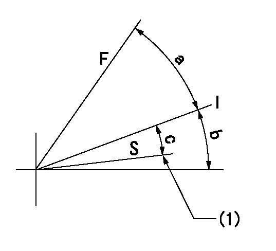
F:Full load
I:Idle
S:Stop
(1)Stopper bolt setting
----------
----------
a=32.5deg+-3deg b=20deg+-5deg c=(10.5deg)+-3deg
----------
----------
a=32.5deg+-3deg b=20deg+-5deg c=(10.5deg)+-3deg
Stop lever angle
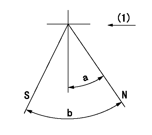
N:Pump normal
S:Stop the pump.
(1)Drive side
----------
----------
a=32deg+-5deg b=64deg+-5deg
----------
----------
a=32deg+-5deg b=64deg+-5deg
Timing setting

(1)Pump vertical direction
(2)Coupling's key groove position at No 1 cylinder's beginning of injection
(3)-
(4)-
----------
----------
a=(150deg)
----------
----------
a=(150deg)
Information:
Starting From External Electrical Source
Always wear protective glasses when working with batteries.Do not allow the free end of booster cables to make contact with each other or touch the engine. This will help prevent sparks near the batteries.Batteries give off flammable fumes that can explode.Do not smoke when observing the battery electrolyte levels.Electrolyte is an acid and can cause personal injury if it contacts skin or eyes.
Be sure the main power switch is in the OFF position before attaching the booster cables to the engine being started. When using booster cables, be sure to connect in parallel: POSITIVE (+) to POSITIVE (+) and NEGATIVE (-) to NEGATIVE (-).Use only equal voltage for boost starting. The use of a welder or higher voltage will damage the electrical system.
Engines without engine-to-frame ground straps can be damaged by electrical discharge.To prevent electrical discharge damage, check to make sure there is an engine-to-frame ground strap. For engines which have the alternator connected to an engine component, the ground strap must connect that component to the frame.Some engines have starter-to-frame ground straps. But, many of these starters are not electrically grounded to the engine. They have electrical insulation systems. For this reason, the starter-to-frame ground strap may not be an acceptable ground.Connect one end of cable to the POSITIVE (+) (ungrounded) terminal of the battery on the engine being started. Connect the other end to the POSITIVE (+) terminal of the power source.Connect one end of the second cable to the NEGATIVE (-) terminal of the power source. Connect the other end to the frame of the engine to be started.Turn the start switch on and start the engine.Disconnect the cable from the frame first. Disconnect the other end from the NEGATIVE (-) terminal of the power source. Disconnect the cable from the POSITIVE (+) terminal of the battery. Disconnect the other end from the POSITIVE (+) terminal of the power source.
Have questions with 106672-9932?
Group cross 106672-9932 ZEXEL
Mitsubishi-Heav
Mitsubishi-Heav
Daewoo
Komatsu
106672-9932
9 400 617 193
6152711992
INJECTION-PUMP ASSEMBLY
SA6D125
SA6D125