Information injection-pump assembly
ZEXEL
106672-9903
1066729903
MITSUBISHI-HEAV
3256570280
3256570280

Rating:
Cross reference number
ZEXEL
106672-9903
1066729903
MITSUBISHI-HEAV
3256570280
3256570280
Zexel num
Bosch num
Firm num
Name
Calibration Data:
Adjustment conditions
Test oil
1404 Test oil ISO4113 or {SAEJ967d}
1404 Test oil ISO4113 or {SAEJ967d}
Test oil temperature
degC
40
40
45
Nozzle and nozzle holder
105780-8130
Bosch type code
EFEP215A
Nozzle
105780-0050
Bosch type code
DN6TD119NP1T
Nozzle holder
105780-2090
Bosch type code
EFEP215
Opening pressure
MPa
17.2
Opening pressure
kgf/cm2
175
Injection pipe
Outer diameter - inner diameter - length (mm) mm 8-3-600
Outer diameter - inner diameter - length (mm) mm 8-3-600
Overflow valve
131424-7420
Overflow valve opening pressure
kPa
255
221
289
Overflow valve opening pressure
kgf/cm2
2.6
2.25
2.95
Tester oil delivery pressure
kPa
157
157
157
Tester oil delivery pressure
kgf/cm2
1.6
1.6
1.6
Direction of rotation (viewed from drive side)
Left L
Left L
Injection timing adjustment
Direction of rotation (viewed from drive side)
Left L
Left L
Injection order
1-5-3-6-
2-4
Pre-stroke
mm
3.9
3.85
3.95
Rack position
Point A R=A
Point A R=A
Beginning of injection position
Governor side NO.1
Governor side NO.1
Difference between angles 1
Cal 1-5 deg. 60 59.5 60.5
Cal 1-5 deg. 60 59.5 60.5
Difference between angles 2
Cal 1-3 deg. 120 119.5 120.5
Cal 1-3 deg. 120 119.5 120.5
Difference between angles 3
Cal 1-6 deg. 180 179.5 180.5
Cal 1-6 deg. 180 179.5 180.5
Difference between angles 4
Cyl.1-2 deg. 240 239.5 240.5
Cyl.1-2 deg. 240 239.5 240.5
Difference between angles 5
Cal 1-4 deg. 300 299.5 300.5
Cal 1-4 deg. 300 299.5 300.5
Injection quantity adjustment
Adjusting point
A
Rack position
15.4
Pump speed
r/min
750
750
750
Average injection quantity
mm3/st.
428
419
437
Max. variation between cylinders
%
0
-3
3
Basic
*
Fixing the lever
*
Injection quantity adjustment_02
Adjusting point
B
Rack position
4.3+-0.5
Pump speed
r/min
425
425
425
Average injection quantity
mm3/st.
22
19
25
Max. variation between cylinders
%
0
-10
10
Fixing the rack
*
Test data Ex:
Governor adjustment
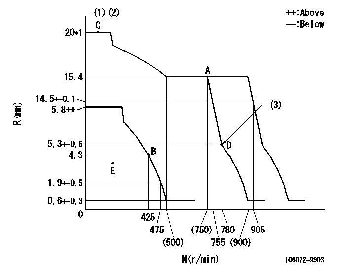
N:Pump speed
R:Rack position (mm)
(1)Target notch: K
(2)Tolerance for racks not indicated: +-0.05mm.
(3)Idle sub spring setting: L1.
----------
K=12 L1=5.3-0.5mm
----------
----------
K=12 L1=5.3-0.5mm
----------
Speed control lever angle
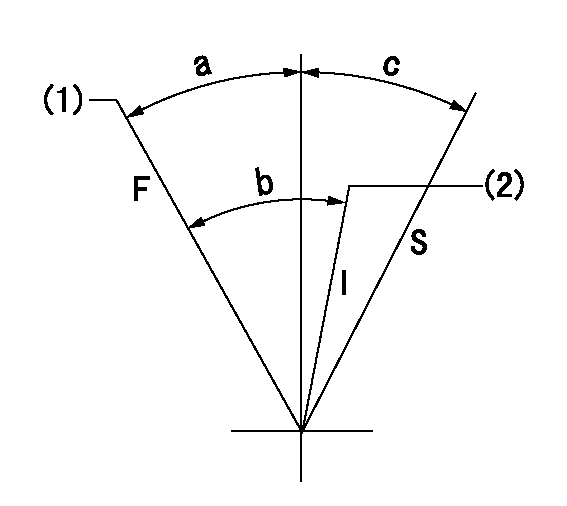
F:Full speed
S:Stop
(1)Set the pump speed at aa. (At delivery)
(2)Pump speed = bb
----------
aa=900r/min bb=750r/min
----------
a=8deg+-5deg c=32deg+-3deg b=9deg+-5deg
----------
aa=900r/min bb=750r/min
----------
a=8deg+-5deg c=32deg+-3deg b=9deg+-5deg
0000000901
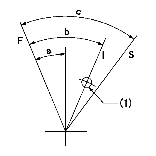
F:Full load
I:Idle
S:Stop
(1)Use the hole at R = aa
----------
aa=25mm
----------
a=26deg+-5deg b=40deg+-5deg c=53deg+-5deg
----------
aa=25mm
----------
a=26deg+-5deg b=40deg+-5deg c=53deg+-5deg
Timing setting

(1)Pump vertical direction
(2)Coupling's key groove position at No 1 cylinder's beginning of injection
(3)-
(4)-
----------
----------
a=(20deg)
----------
----------
a=(20deg)
Information:
Final Fuel Filter
The filter element collects and holds contaminants and cannot be washed or otherwise restored.To remove the used filter, proceed as follows:1. Stop the engine and close the diesel fuel line valve (if equipped).2. Unscrew and remove filter. 3. Clean the gasket sealing surfaces on the filter bases. 4. Lubricate the new filter gasket with clean diesel fuel.
Do not pour fuel into the new filter element before installing. Prime the system as instructed in the topic, PRIMING THE FUEL SYSTEM.
5. Tighten the filter by hand until the gasket contacts the base, then tighten 1/2 to 3/4 turn more.6. Start the engine and run at 1000 rpm for several minutes and check for leaks. If the engine fails to start, prime the fuel system. See the topic TO PRIME THE SYSTEM. Keep New Fuel Filters On Hand
Extra filters should be kept on hand for replacement. Always keep filters wrapped in their original carton to insure against dust and dirt accumulation which will shorten the life of the filters or may cause damage to the fuel injection equipment.To Prime The System
If air is trapped in the fuel system, the diesel engine will either not start, or will misfire. Then it is necessary to prime the system.The fuel priming pump is mounted on the fuel filter base. If the fuel filter is changed or if the engine has run out of fuel, prime the fuel system as follows: 1. Be sure the fuel line valve is open and the engine shutoff control is off.2. Unlock the fuel priming pump.3. Operate priming pump until increased resistance is felt.4. Lock fuel priming pump.If the engine fails to start or continues to misfire or smoke, further bleeding is necessary. With engine running, or with the use of the priming pump, loosen fuel line nuts, one at a time, several times in succession and allow fuel to run until free of air bubbles. Tighten fuel line nuts.
LOOSENING FUEL INJECTION LINE TO BLEED SYSTEMFuel Injection Equipment
When improper fuel injection is affecting engine operation, a systematic check should be made to determine the cause. The most likely cause is dirt or water in the fuel. Drain the sediment from the fuel tank. Check the fuel pressure gauge as mentioned in the topic, FUEL FILTERING SYSTEM. Replace the filters if necessary. Then prime the fuel system until clean fuel reaches the fuel injection pumps. If the fuel system is air bound, priming the system will overcome the difficulty.If the engine is running irregularly, smoking, or knocking, a fuel injection valve may not be spraying the fuel properly.Direct Injection System
The fuel system of direct injection engines is essentially the same as precombustion chamber engines. The absence of the precombustion chamber requires a different fuel nozzle and adapter. Externally the direct injection fuel nozzle resembles the precombustion chamber nozzle except it is longer in length. Nozzle testing and replacement procedure is the same as illustrated for the precombustion chamber engines, except that an extracting tool is used to remove