Information injection-pump assembly
ZEXEL
106672-9780
1066729780
Rating:
Service parts 106672-9780 INJECTION-PUMP ASSEMBLY:
1.
_
5.
AUTOM. ADVANCE MECHANIS
7.
COUPLING PLATE
8.
_
9.
_
11.
Nozzle and Holder
6-15211-310-0
12.
Open Pre:MPa(Kqf/cm2)
24.5(250)
15.
NOZZLE SET
Include in #1:
106672-9780
as INJECTION-PUMP ASSEMBLY
Cross reference number
ZEXEL
106672-9780
1066729780
Zexel num
Bosch num
Firm num
Name
106672-9780
INJECTION-PUMP ASSEMBLY
Calibration Data:
Adjustment conditions
Test oil
1404 Test oil ISO4113 or {SAEJ967d}
1404 Test oil ISO4113 or {SAEJ967d}
Test oil temperature
degC
40
40
45
Nozzle and nozzle holder
105780-8130
Bosch type code
EFEP215A
Nozzle
105780-0050
Bosch type code
DN6TD119NP1T
Nozzle holder
105780-2090
Bosch type code
EFEP215
Opening pressure
MPa
17.2
Opening pressure
kgf/cm2
175
Injection pipe
Outer diameter - inner diameter - length (mm) mm 8-3-600
Outer diameter - inner diameter - length (mm) mm 8-3-600
Overflow valve opening pressure
kPa
157
123
191
Overflow valve opening pressure
kgf/cm2
1.6
1.25
1.95
Tester oil delivery pressure
kPa
157
157
157
Tester oil delivery pressure
kgf/cm2
1.6
1.6
1.6
Direction of rotation (viewed from drive side)
Left L
Left L
Injection timing adjustment
Direction of rotation (viewed from drive side)
Left L
Left L
Injection order
1-5-3-6-
2-4
Pre-stroke
mm
3.8
3.75
3.85
Beginning of injection position
Drive side NO.1
Drive side NO.1
Difference between angles 1
Cal 1-5 deg. 60 59.5 60.5
Cal 1-5 deg. 60 59.5 60.5
Difference between angles 2
Cal 1-3 deg. 120 119.5 120.5
Cal 1-3 deg. 120 119.5 120.5
Difference between angles 3
Cal 1-6 deg. 180 179.5 180.5
Cal 1-6 deg. 180 179.5 180.5
Difference between angles 4
Cyl.1-2 deg. 240 239.5 240.5
Cyl.1-2 deg. 240 239.5 240.5
Difference between angles 5
Cal 1-4 deg. 300 299.5 300.5
Cal 1-4 deg. 300 299.5 300.5
Injection quantity adjustment
Adjusting point
A
Rack position
12.8
Pump speed
r/min
700
700
700
Average injection quantity
mm3/st.
305.4
303.4
307.4
Max. variation between cylinders
%
0
-3
3
Basic
*
Fixing the lever
*
Injection quantity adjustment_02
Adjusting point
B
Rack position
5.7+-0.5
Pump speed
r/min
375
375
375
Average injection quantity
mm3/st.
14.6
13.1
16.1
Max. variation between cylinders
%
0
-15
15
Fixing the rack
*
Test data Ex:
Governor adjustment
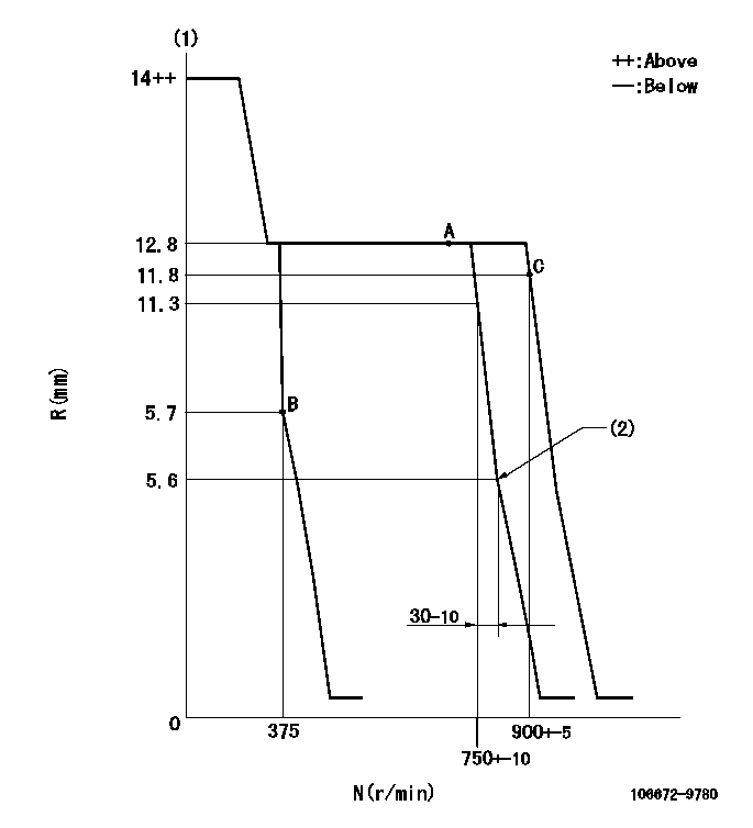
N:Pump speed
R:Rack position (mm)
(1)Target notch: K
(2)Idle sub spring setting: L1.
----------
K=12 L1=5.6-0.5mm
----------
----------
K=12 L1=5.6-0.5mm
----------
Speed control lever angle
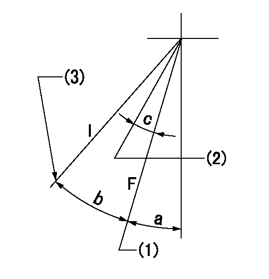
F:Full speed
I:Idle
(1)Speed set at aa (setting at shipping)
(2)Set the pump speed at bb.
(3)Stopper bolt setting
----------
aa=900r/min bb=750r/min
----------
a=2deg+-5deg b=22deg+-5deg c=6deg+-5deg
----------
aa=900r/min bb=750r/min
----------
a=2deg+-5deg b=22deg+-5deg c=6deg+-5deg
Stop lever angle
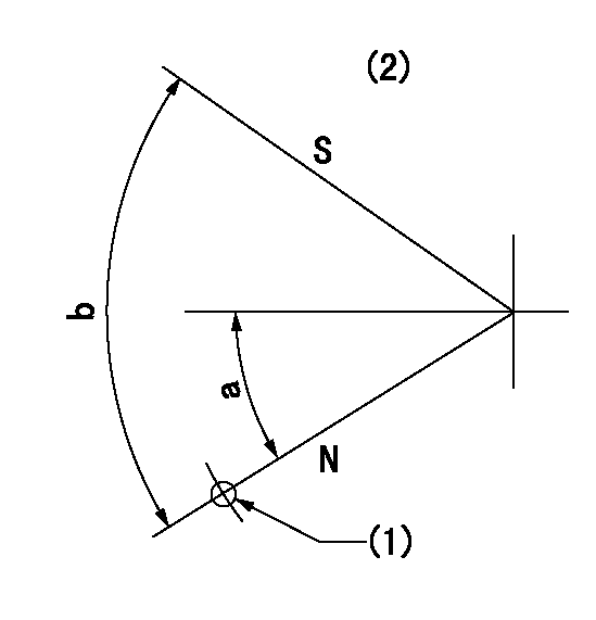
N:Pump normal
S:Stop the pump.
(1)Use hole at R = aa (left hand side)
(2)No return spring
----------
aa=27mm
----------
a=26.5deg+-5deg b=53deg+-5deg
----------
aa=27mm
----------
a=26.5deg+-5deg b=53deg+-5deg
Timing setting

(1)Pump vertical direction
(2)Coupling's key groove position at No 1 cylinder's beginning of injection
(3)-
(4)-
----------
----------
a=(150deg)
----------
----------
a=(150deg)
Information:
1. Remove tube and elbow (1).2. Remove tube and oil sump (2). 3. Turn the crankshaft until two of the pistons are at top center and two are at bottom center.
Put identification marks on the connecting rod caps as to their location in the engine. Keep the caps with their respective piston.
4. Remove nuts (3), and remove connecting rod bearing cap (4).5. Remove the lower bearing half from the connecting rod cap. Push the connecting rod away from the crankshaft, and remove the upper bearing half.
Use tape to hold the bearing halves together and to identify the number of the cylinder.
6. Install the upper bearings in the connecting rods. Be sure the tab on the back of the bearing fits in the groove of the connecting rod. Install the connecting rod bearings dry when the clearance checks are made. Put clean engine oil on the connecting rod bearings for final assembly.7. Carefully pull the connecting rods onto the crankshaft.8. Install the lower bearings in the connecting rod caps. Be sure the tab on the back of the bearing fits the groove of the cap.9. Check the bearing clearance with Plastigage as follows:a. Put clean oil on the connecting rod bolt threads.b. Align the number on bearing cap (4) with the number on the connecting rod, and install bearing cap (4) with a line of Plastigage across the bearing.c. Install the nuts finger tight; then tighten them to a torque of 100 N m (75 lb.ft.).d. Remove the connecting rod cap, and measure the thickness of the Plastigage to the bearing clearances. See Engine Specifications for correct bearing clearances.e. Carefully move the connecting rod up enough to permit clean engine oil to be put on the upper bearing and crankshaft journal.f. Carefully pull the connecting rod onto the crankshaft.g. Install connecting rod cap (4), and tighten the nuts to the proper torque. The Cadmium plated nuts (silver color) are to be tightened to a torque of 100 N m (75 lb.ft.). The Phosphated nuts (dull black color) are to be tightened to a torque of 130 N m (95 lb.ft.).h. Repeat the procedure for the remainder of the connecting rods.10. Install tube and elbow (1) and tube and oil sump (2).End By:a. install oil pan
Have questions with 106672-9780?
Group cross 106672-9780 ZEXEL
106672-9780
INJECTION-PUMP ASSEMBLY