Information injection-pump assembly
ZEXEL
106672-9710
1066729710
Rating:
Service parts 106672-9710 INJECTION-PUMP ASSEMBLY:
1.
_
5.
AUTOM. ADVANCE MECHANIS
6.
COUPLING PLATE
7.
COUPLING PLATE
8.
_
9.
_
11.
Nozzle and Holder
12.
Open Pre:MPa(Kqf/cm2)
22.6{230}

15.
NOZZLE SET
Include in #1:
106672-9710
as INJECTION-PUMP ASSEMBLY
Cross reference number
ZEXEL
106672-9710
1066729710
Zexel num
Bosch num
Firm num
Name
106672-9710
INJECTION-PUMP ASSEMBLY
Calibration Data:
Adjustment conditions
Test oil
1404 Test oil ISO4113 or {SAEJ967d}
1404 Test oil ISO4113 or {SAEJ967d}
Test oil temperature
degC
40
40
45
Nozzle and nozzle holder
105780-8140
Bosch type code
EF8511/9A
Nozzle
105780-0000
Bosch type code
DN12SD12T
Nozzle holder
105780-2080
Bosch type code
EF8511/9
Opening pressure
MPa
17.2
Opening pressure
kgf/cm2
175
Injection pipe
Outer diameter - inner diameter - length (mm) mm 8-3-600
Outer diameter - inner diameter - length (mm) mm 8-3-600
Overflow valve
132424-0620
Overflow valve opening pressure
kPa
157
123
191
Overflow valve opening pressure
kgf/cm2
1.6
1.25
1.95
Tester oil delivery pressure
kPa
157
157
157
Tester oil delivery pressure
kgf/cm2
1.6
1.6
1.6
Direction of rotation (viewed from drive side)
Right R
Right R
Injection timing adjustment
Direction of rotation (viewed from drive side)
Right R
Right R
Injection order
1-4-2-6-
3-5
Pre-stroke
mm
3.3
3.25
3.35
Beginning of injection position
Drive side NO.1
Drive side NO.1
Difference between angles 1
Cal 1-4 deg. 60 59.5 60.5
Cal 1-4 deg. 60 59.5 60.5
Difference between angles 2
Cyl.1-2 deg. 120 119.5 120.5
Cyl.1-2 deg. 120 119.5 120.5
Difference between angles 3
Cal 1-6 deg. 180 179.5 180.5
Cal 1-6 deg. 180 179.5 180.5
Difference between angles 4
Cal 1-3 deg. 240 239.5 240.5
Cal 1-3 deg. 240 239.5 240.5
Difference between angles 5
Cal 1-5 deg. 300 299.5 300.5
Cal 1-5 deg. 300 299.5 300.5
Injection quantity adjustment
Adjusting point
A
Rack position
10.5
Pump speed
r/min
900
900
900
Each cylinder's injection qty
mm3/st.
151.2
148.6
153.8
Basic
*
Fixing the rack
*
Injection quantity adjustment_02
Adjusting point
-
Rack position
6.3+-0.5
Pump speed
r/min
250
250
250
Each cylinder's injection qty
mm3/st.
15
13.5
16.5
Fixing the rack
*
Remarks
Adjust only variation between cylinders; adjust governor according to governor specifications.
Adjust only variation between cylinders; adjust governor according to governor specifications.
Test data Ex:
Governor adjustment
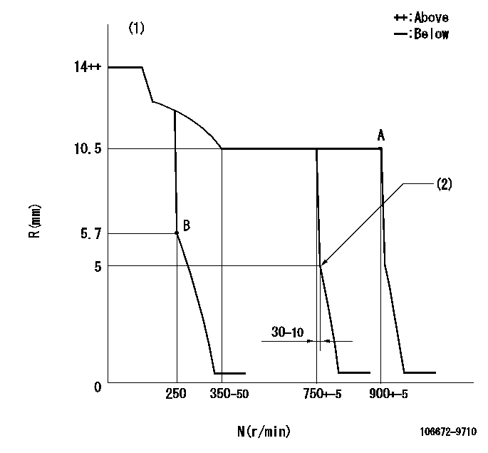
N:Pump speed
R:Rack position (mm)
(1)Target notch: K
(2)Idle sub spring setting: L1.
----------
K=15 L1=5-0.5mm
----------
----------
K=15 L1=5-0.5mm
----------
Speed control lever angle
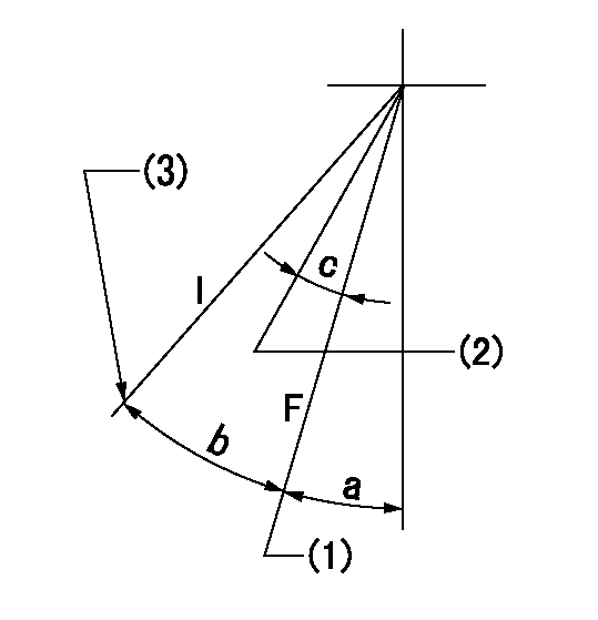
F:Full speed
I:Idle
(1)Set the pump speed at aa
(2)Set the pump speed at bb.
(3)Stopper bolt setting
----------
aa=900r/min bb=750r/min
----------
a=19deg+-5deg b=28deg+-5deg c=7deg+-5deg
----------
aa=900r/min bb=750r/min
----------
a=19deg+-5deg b=28deg+-5deg c=7deg+-5deg
Stop lever angle

N:Pump normal
S:Stop the pump.
----------
----------
a=20deg+-5deg b=53deg+-5deg
----------
----------
a=20deg+-5deg b=53deg+-5deg
Timing setting

(1)Pump vertical direction
(2)Position of camshaft's key groove at No 1 cylinder's beginning of injection
(3)-
(4)-
----------
----------
a=(50deg)
----------
----------
a=(50deg)
Information:
Start By:a. remove timing gear case cover1. Put the No. 1 piston at top dead center on the compression stroke. Be sure all the timing marks are in alignment with each other. 2. Remove plate (2) that holds idler gear (1). 3. Remove idler gear (1). 4. Inspect two bushings (3) in idler gear (1). See Engine Specifications for bushing diameter. Remove two bushings (3) if replacement is necessary. 5. Remove fuel injection pump drive gear (4). 6. Bend lock (5) away from the bolt. Remove the bolt and remove washer (6). 7. Remove camshaft drive gear (7) with tool (A).Install Timing Gears
1. Align the slot in gear (1) with the key in the camshaft. Put the camshaft gear in position on the camshaft. 2. Install washer (2), lock (3) and the bolt. Tighten the bolt to a torque of 60-70 N m (45-52 lb ft). Bend the tab of the lock against the bolt head. 3. Align the roll pin in fuel injection pump drive gear (4) with the hole in fuel injection pump drive shaft (5). Install fuel injection pump drive gear (4) on to fuel injection pump drive shaft (5). 4. Install three bolts (6) to hold drive gear (4) to the fuel injection pump drive shaft. 5. Use tool (A) to install two bushings (7) into idler gear (8). Install the bushings even with the outside of idler gear (8). 6. Align the timing marks on idler gear (8) with the crankshaft gear, camshaft drive gear and the fuel injection pump drive gear. 7. Install plate (9) and the bolts to hold idler gear (8) on the idler gear shaft. Tighten the three bolts to a torque of 40 N m (30 lb ft). 8. Check the idler gear end clearance. The clearance must be at least 0.25 mm (.010 in). 9. Fasten a steel plate to the timing gear case. Fasten tooling (A) to the plate as shown. Check the timing gear backlash. The backlash must be 0.08 - 0.15 mm (.003 - .006 in).
1. Align the slot in gear (1) with the key in the camshaft. Put the camshaft gear in position on the camshaft. 2. Install washer (2), lock (3) and the bolt. Tighten the bolt to a torque of 60-70 N m (45-52 lb ft). Bend the tab of the lock against the bolt head. 3. Align the roll pin in fuel injection pump drive gear (4) with the hole in fuel injection pump drive shaft (5). Install fuel injection pump drive gear (4) on to fuel injection pump drive shaft (5). 4. Install three bolts (6) to hold drive gear (4) to the fuel injection pump drive shaft. 5. Use tool (A) to install two bushings (7) into idler gear (8). Install the bushings even with the outside of idler gear (8). 6. Align the timing marks on idler gear (8) with the crankshaft gear, camshaft drive gear and the fuel injection pump drive gear. 7. Install plate (9) and the bolts to hold idler gear (8) on the idler gear shaft. Tighten the three bolts to a torque of 40 N m (30 lb ft). 8. Check the idler gear end clearance. The clearance must be at least 0.25 mm (.010 in). 9. Fasten a steel plate to the timing gear case. Fasten tooling (A) to the plate as shown. Check the timing gear backlash. The backlash must be 0.08 - 0.15 mm (.003 - .006 in).
Have questions with 106672-9710?
Group cross 106672-9710 ZEXEL
Yanmar
106672-9710
INJECTION-PUMP ASSEMBLY