Information injection-pump assembly
ZEXEL
106672-9700
1066729700

Rating:
Cross reference number
ZEXEL
106672-9700
1066729700
Zexel num
Bosch num
Firm num
Name
106672-9700
INJECTION-PUMP ASSEMBLY
Calibration Data:
Adjustment conditions
Test oil
1404 Test oil ISO4113 or {SAEJ967d}
1404 Test oil ISO4113 or {SAEJ967d}
Test oil temperature
degC
40
40
45
Nozzle and nozzle holder
105780-8140
Bosch type code
EF8511/9A
Nozzle
105780-0000
Bosch type code
DN12SD12T
Nozzle holder
105780-2080
Bosch type code
EF8511/9
Opening pressure
MPa
17.2
Opening pressure
kgf/cm2
175
Injection pipe
Outer diameter - inner diameter - length (mm) mm 8-3-600
Outer diameter - inner diameter - length (mm) mm 8-3-600
Overflow valve
132424-0620
Overflow valve opening pressure
kPa
157
123
191
Overflow valve opening pressure
kgf/cm2
1.6
1.25
1.95
Tester oil delivery pressure
kPa
157
157
157
Tester oil delivery pressure
kgf/cm2
1.6
1.6
1.6
Direction of rotation (viewed from drive side)
Right R
Right R
Injection timing adjustment
Direction of rotation (viewed from drive side)
Right R
Right R
Injection order
1-4-2-6-
3-5
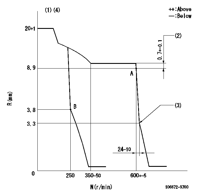
Pre-stroke
mm
3.3
3.25
3.35
Beginning of injection position
Drive side NO.1
Drive side NO.1
Difference between angles 1
Cal 1-4 deg. 60 59.5 60.5
Cal 1-4 deg. 60 59.5 60.5
Difference between angles 2
Cyl.1-2 deg. 120 119.5 120.5
Cyl.1-2 deg. 120 119.5 120.5
Difference between angles 3
Cal 1-6 deg. 180 179.5 180.5
Cal 1-6 deg. 180 179.5 180.5
Difference between angles 4
Cal 1-3 deg. 240 239.5 240.5
Cal 1-3 deg. 240 239.5 240.5
Difference between angles 5
Cal 1-5 deg. 300 299.5 300.5
Cal 1-5 deg. 300 299.5 300.5
Injection quantity adjustment
Adjusting point
A
Rack position
8.9
Pump speed
r/min
600
600
600
Each cylinder's injection qty
mm3/st.
140.5
138.1
142.9
Basic
*
Fixing the lever
*
Injection quantity adjustment_02
Adjusting point
B
Rack position
3.8+-0.5
Pump speed
r/min
250
250
250
Each cylinder's injection qty
mm3/st.
14.9
13.4
16.4
Fixing the rack
*
Test data Ex:
Governor adjustment
N:Pump speed
R:Rack position (mm)
(1)Target notch: K
(2)Rack difference between N = N1 and N = N2
(3)Idle sub spring setting: L1.
(4)Confirm that the rack is pulled back to R = R1 or less at solenoid operation (N = 0).
----------
K=10 N1=600r/min N2=500r/min L1=3.3-0.5mm R1=3.3mm
----------
----------
K=10 N1=600r/min N2=500r/min L1=3.3-0.5mm R1=3.3mm
----------
Speed control lever angle
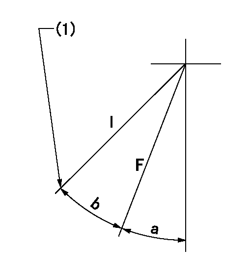
F:Full speed
I:Idle
(1)Stopper bolt setting
----------
----------
a=19deg+-5deg b=24deg+-5deg
----------
----------
a=19deg+-5deg b=24deg+-5deg
Stop lever angle

N:Pump normal
S:Stop the pump.
----------
----------
a=20deg+-5deg b=53deg+-5deg
----------
----------
a=20deg+-5deg b=53deg+-5deg
Timing setting

(1)Pump vertical direction
(2)Position of camshaft's key groove at No 1 cylinder's beginning of injection
(3)-
(4)-
----------
----------
a=(50deg)
----------
----------
a=(50deg)
Information:
Start By:a. remove radiator 1. Remove the four bolts and remove fan blade (1) and extension. 2. Loosen bolts (2) and remove fan belt (4). Loosen clamps (3) and disconnect the two hoses. Remove nut (5) from water pump fan pulley (6). 3. Install tooling (A) and remove fan pulley (6). 4. Remove four bolts (7) and remove the water pump and gasket. At the time of assembly, tighten nut (5) to the torque of 80 N m (60 lb.ft.) Install in the reverse order.Disassemble Water Pump
Start By:a. remove water pump 1. Remove key (1) from the shaft. 2. Remove pump housing (2) from the rear housing. 3. Remove snap ring (3) with tool (A). 4. Put the water pump housing in position on a press. Install tool (B) and remove the shaft assembly from the impeller and water pump housing. 5. Remove seals (4) from the water pump housing if they are damaged. 6. Put shaft assembly (5) in position in a press. Install tool (B) and remove bearings (6) and spacer (7) from the shaft.Assemble Water Pump
1. Put one of the shaft's bearings in position in a press. Make sure there is support for the inner race of the bearing. Push shaft (1) on to bearing (2). 2. Install spacer (4) on the shaft. Put second bearing (3) in position and push the shaft on to it. 3. Install seal (6) and flange (5) in the water pump housing. 4. Put 2S3230 Bearing Lubricant on the bearings. Put the water pump housing in position on a press and install shaft assembly (7) in the housing. 5. Install snap ring (8) over the bearings with tool (A). 6. Install the water seal in the housing with tooling (B). 7. Install seal (9) on the shaft assembly. 8. Install impeller (10) on the shaft with tooling (C) and a press. The clearance between the impeller blade and pump body must be 0.30 to 0.81 mm (.012 to .032 in). 9. Install a new gasket on water pump housing (12). Install housing (12) on the rear housing with nuts (11) that hold it. 10. Install key (13) in the shaft.End By:a. install water pump
Have questions with 106672-9700?
Group cross 106672-9700 ZEXEL
106672-9700
INJECTION-PUMP ASSEMBLY