Information injection-pump assembly
ZEXEL
106672-9551
1066729551
KOMATSU
6128711120
6128711120
Rating:
Cross reference number
ZEXEL
106672-9551
1066729551
KOMATSU
6128711120
6128711120
Zexel num
Bosch num
Firm num
Name
Calibration Data:
Adjustment conditions
Test oil
1404 Test oil ISO4113 or {SAEJ967d}
1404 Test oil ISO4113 or {SAEJ967d}
Test oil temperature
degC
40
40
45
Nozzle and nozzle holder
105780-8130
Bosch type code
EFEP215A
Nozzle
105780-0050
Bosch type code
EN6TD119NP1T
Nozzle holder
105780-2090
Bosch type code
EFEP215
Opening pressure
MPa
17.2
Opening pressure
kgf/cm2
175
Injection pipe
Outer diameter - inner diameter - length (mm) mm 8-3-600
Outer diameter - inner diameter - length (mm) mm 8-3-600
Overflow valve
131425-1620
Overflow valve opening pressure
kPa
255
221
289
Overflow valve opening pressure
kgf/cm2
2.6
2.25
2.95
Tester oil delivery pressure
kPa
157
157
157
Tester oil delivery pressure
kgf/cm2
1.6
1.6
1.6
Direction of rotation (viewed from drive side)
Right R
Right R
Injection timing adjustment
Direction of rotation (viewed from drive side)
Right R
Right R
Injection order
1-5-3-6-
2-4
Pre-stroke
mm
2.5
2.45
2.55
Beginning of injection position
Drive side NO.1
Drive side NO.1
Difference between angles 1
Cal 1-5 deg. 60 59.5 60.5
Cal 1-5 deg. 60 59.5 60.5
Difference between angles 2
Cal 1-3 deg. 120 119.5 120.5
Cal 1-3 deg. 120 119.5 120.5
Difference between angles 3
Cal 1-6 deg. 180 179.5 180.5
Cal 1-6 deg. 180 179.5 180.5
Difference between angles 4
Cyl.1-2 deg. 240 239.5 240.5
Cyl.1-2 deg. 240 239.5 240.5
Difference between angles 5
Cal 1-4 deg. 300 299.5 300.5
Cal 1-4 deg. 300 299.5 300.5
Injection quantity adjustment
Adjusting point
A
Rack position
15.3
Pump speed
r/min
1000
1000
1000
Each cylinder's injection qty
mm3/st.
351
344
358
Basic
*
Fixing the lever
*
Boost pressure
kPa
62.7
62.7
Boost pressure
mmHg
470
470
Injection quantity adjustment_02
Adjusting point
B
Rack position
15.9+-0.
5
Pump speed
r/min
700
700
700
Average injection quantity
mm3/st.
339
329
349
Fixing the lever
*
Boost pressure
kPa
62.7
62.7
Boost pressure
mmHg
470
470
Injection quantity adjustment_03
Adjusting point
C
Rack position
R2-1.6
Pump speed
r/min
400
400
400
Average injection quantity
mm3/st.
285
275
295
Fixing the lever
*
Boost pressure
kPa
0
0
0
Boost pressure
mmHg
0
0
0
Injection quantity adjustment_04
Adjusting point
D
Rack position
6.5+-0.5
Pump speed
r/min
300
300
300
Average injection quantity
mm3/st.
31
27
35
Max. variation between cylinders
%
0
-10
10
Fixing the rack
*
Boost pressure
kPa
0
0
0
Boost pressure
mmHg
0
0
0
Injection quantity adjustment_05
Adjusting point
E
Rack position
-
Pump speed
r/min
100
100
100
Average injection quantity
mm3/st.
295
285
305
Fixing the lever
*
Boost pressure
kPa
0
0
0
Boost pressure
mmHg
0
0
0
Rack limit
*
Boost compensator adjustment
Pump speed
r/min
400
400
400
Rack position
R2-1.6
Boost pressure
kPa
18.7
17.4
21.4
Boost pressure
mmHg
140
130
160
Boost compensator adjustment_02
Pump speed
r/min
400
400
400
Rack position
R2(16)
Boost pressure
kPa
49.3
42.6
56
Boost pressure
mmHg
370
320
420
Test data Ex:
Governor adjustment
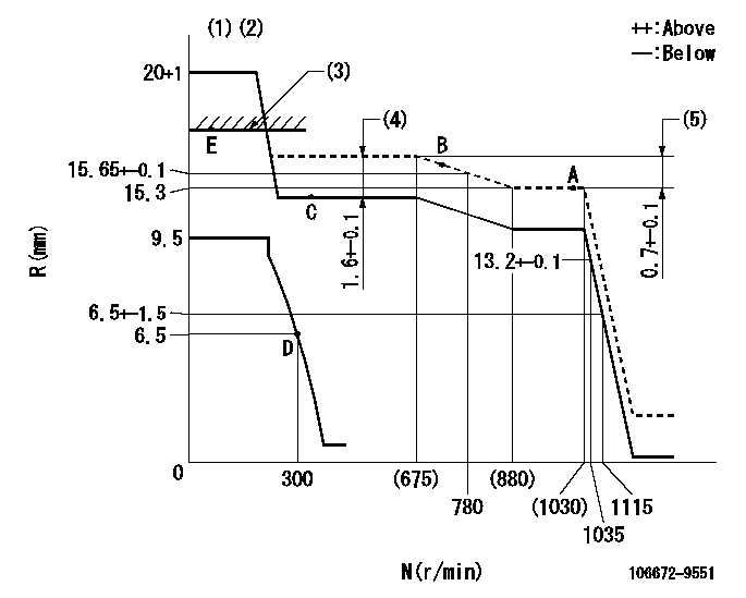
N:Pump speed
R:Rack position (mm)
(1)Target notch: K
(2)Tolerance for racks not indicated: +-0.05mm.
(3)RACK LIMIT
(4)Boost compensator stroke
(5)Rack difference between N = N1 and N = N2
----------
K=20 N1=1000r/min N2=400r/min
----------
----------
K=20 N1=1000r/min N2=400r/min
----------
Speed control lever angle
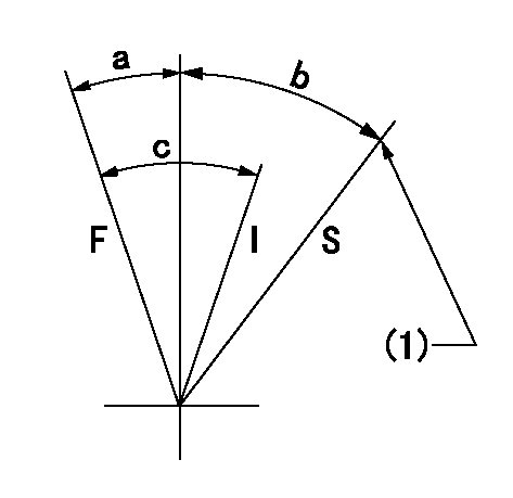
F:Full speed
I:Idle
S:Stop
(1)Stopper bolt setting
----------
----------
a=(16.5deg)+-5deg b=31deg+-3deg c=(32deg)+-5deg
----------
----------
a=(16.5deg)+-5deg b=31deg+-3deg c=(32deg)+-5deg
Timing setting

(1)Pump vertical direction
(2)Position of spline gear's aligning mark at No 1 cylinder's beginning of injection (key position)
(3)-
(4)-
----------
----------
a=(50deg)
----------
----------
a=(50deg)
Information:
D3, 910 and 931
(1) Use two S509 Bolts with 5P4116 Washers to fasten 5G657 Plate (1) to the inside of the radiator guard, in the holes drilled on either page 3 or 4.(2) Install 5P6315 Elbow (2) in 6N7673 Valve Assembly (3). Use 1C569 Bolts with 4B3849 Washers to fasten 6N7673 Valve Assembly (3) and 7N2059 Clamp (4) to plate (1). Use a 5P6314 Sleeve and 5P6313 Nut to connect 5G659 Tube (5) to elbow (2).(3) Remove the plug from the top of air inlet pipe (6) and install 6N7672 Atomizer (7) so the orifice is down (toward the manifold). Connect 7N140 Tube Assembly (8) and 5G660 Tube (9) to tube (5) and atomizer (7) as shown. Put a 3D5102 Grommet on tube (9) and use 8M2772 Clip (10) with an existing valve cover bolt for support of the tube. Tighten the bolt according to valve cover bolt specifications.(4) Remove plug (11) from the heater hose opening on the top left side of the engine timing gear housing (12). Install 6N5899 Switch (13) in the hole for plug (11). Connect 5G663 Wire (14) to switch (13) and one of the wires on valve assembly (3) as shown.(5) For D3 and 931 Machines, connect one end of 5G689 Wire Assembly (15) to the other wire from valve assembly (3). Use the clips that hold wiring harness (16) to fasten wire assembly (15) as shown, and pull the loose end of wire assembly (15) to the start switch. Do not connect wire assembly (15) to the start switch at this time. For 910 Machines, use 161.5" (41 dm) of 5P629 Wire, one 2L8076 Terminal and one 6K1828 Connector to make a wire assembly (15). (6) For all machines, install 3F1006 Switch (17) in the .656" Ø (16.7 Ø) hole that was drilled in the dash. For all earlier D3 and 931 Machines, and for 910 Machines, 80U1-80U3666, remove the 6S4355 Heat-Start Switch and install 6N8941 Start Switch (18). Put electrical tape on the end of the glow plug wire.(7) Connect 6S9586 Wire Assembly (19) to switch (17) and to the accessory (AC) connection on start switch (18). Connect wire (15), from 6N7673 Valve Assembly (3), to the other connection on switch (17) as shown.(8) Install the ether cylinder assembly and fasten it in position with the 7N2059 Clamp (4) that was installed in step 2.(9) Install a 6S9542 Instruction Film in the location that follows: D3, 931 - Install on the dash above switch (17); 910 - Install on the dash at the right side of switch (17).Installation Of 1W162 Engine Arrangement In 910 Machines As Replacement For: (4N303 Engine Arrangement - 80U1-80U6734), (7N3700 Engine Arrangement - 80U6735-up), (7N9433 Or 1W161 Engine Arrangement - 40Y), (7N9437 Or 1W163 Engine Arrangement - 41Y)
Before installation of the 1W162 Engine Arrangement as a replacement for any of the engine arrangements given above, some changes must be made to the new engine arrangement. See the information that follows. After engine installation is complete,