Information injection-pump assembly
ZEXEL
106672-9410
1066729410
Rating:
Cross reference number
ZEXEL
106672-9410
1066729410
Zexel num
Bosch num
Firm num
Name
Calibration Data:
Adjustment conditions
Test oil
1404 Test oil ISO4113 or {SAEJ967d}
1404 Test oil ISO4113 or {SAEJ967d}
Test oil temperature
degC
40
40
45
Nozzle and nozzle holder
105780-8130
Bosch type code
EFEP215A
Nozzle
105780-0050
Bosch type code
DN6TD119NP1T
Nozzle holder
105780-2090
Bosch type code
EFEP215
Opening pressure
MPa
17.2
Opening pressure
kgf/cm2
175
Injection pipe
Outer diameter - inner diameter - length (mm) mm 8-3-600
Outer diameter - inner diameter - length (mm) mm 8-3-600
Overflow valve
131424-3420
Overflow valve opening pressure
kPa
255
221
289
Overflow valve opening pressure
kgf/cm2
2.6
2.25
2.95
Tester oil delivery pressure
kPa
157
157
157
Tester oil delivery pressure
kgf/cm2
1.6
1.6
1.6
Direction of rotation (viewed from drive side)
Right R
Right R
Injection timing adjustment
Direction of rotation (viewed from drive side)
Right R
Right R
Injection order
1-5-3-6-
2-4
Pre-stroke
mm
4.3
4.25
4.35
Beginning of injection position
Drive side NO.1
Drive side NO.1
Difference between angles 1
Cal 1-5 deg. 60 59.5 60.5
Cal 1-5 deg. 60 59.5 60.5
Difference between angles 2
Cal 1-3 deg. 120 119.5 120.5
Cal 1-3 deg. 120 119.5 120.5
Difference between angles 3
Cal 1-6 deg. 180 179.5 180.5
Cal 1-6 deg. 180 179.5 180.5
Difference between angles 4
Cyl.1-2 deg. 240 239.5 240.5
Cyl.1-2 deg. 240 239.5 240.5
Difference between angles 5
Cal 1-4 deg. 300 299.5 300.5
Cal 1-4 deg. 300 299.5 300.5
Injection quantity adjustment
Adjusting point
A
Rack position
14
Pump speed
r/min
1050
1050
1050
Average injection quantity
mm3/st.
267.4
265.4
269.4
Max. variation between cylinders
%
0
-3
3
Basic
*
Fixing the lever
*
Boost pressure
kPa
53.3
53.3
Boost pressure
mmHg
400
400
Injection quantity adjustment_02
Adjusting point
B
Rack position
6.4+-0.5
Pump speed
r/min
375
375
375
Average injection quantity
mm3/st.
20.6
19.1
22.1
Max. variation between cylinders
%
0
-15
15
Fixing the rack
*
Boost pressure
kPa
0
0
0
Boost pressure
mmHg
0
0
0
Boost compensator adjustment
Pump speed
r/min
400
400
400
Rack position
13
Boost pressure
kPa
6.7
4
9.4
Boost pressure
mmHg
50
30
70
Boost compensator adjustment_02
Pump speed
r/min
400
400
400
Rack position
14.9
Boost pressure
kPa
40
33.3
46.7
Boost pressure
mmHg
300
250
350
Test data Ex:
Governor adjustment
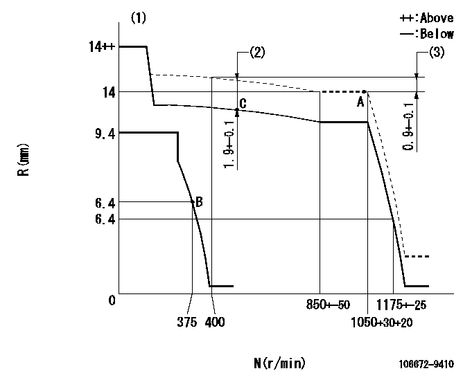
N:Pump speed
R:Rack position (mm)
(1)Target notch: K
(2)Boost compensator stroke
(3)Rack difference between N = N1 and N = N2
----------
K=9 N1=1050r/min N2=400r/min
----------
----------
K=9 N1=1050r/min N2=400r/min
----------
Speed control lever angle
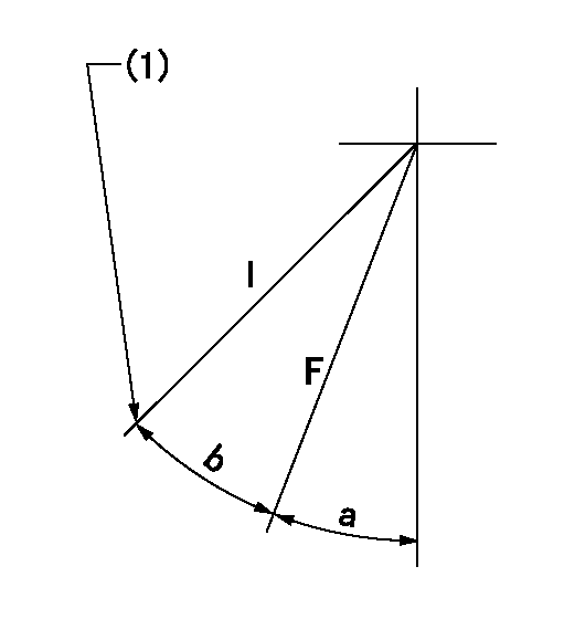
F:Full speed
I:Idle
(1)Stopper bolt setting
----------
----------
a=(38deg)+-5deg b=(25deg)+-5deg
----------
----------
a=(38deg)+-5deg b=(25deg)+-5deg
Stop lever angle
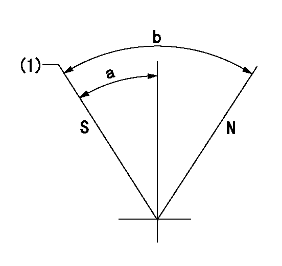
N:Pump normal
S:Stop the pump.
(1)Speed = aa, rack position = bb (sealed at shipping)
----------
aa=0r/min bb=1-0.2mm
----------
a=26.5deg+-5deg b=70deg+-5deg
----------
aa=0r/min bb=1-0.2mm
----------
a=26.5deg+-5deg b=70deg+-5deg
Timing setting
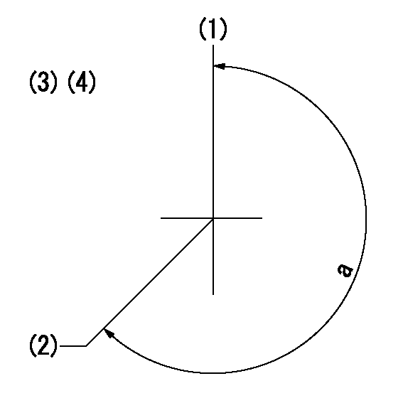
(1)Pump vertical direction
(2)Coupling's key groove position at No 1 cylinder's beginning of injection
(3)-
(4)-
----------
----------
a=(260deg)
----------
----------
a=(260deg)
Information:
The information supplied in this service letter may not be valid after the termination date of this program. Do not perform the work outlined in this Service Letter after the termination date without first contacting your Caterpillar product analyst.
This Program must be administered as soon as possible. When reporting the repair, use "PI3841" as the Part Number, "7751" as the Group Number, "56" as the Warranty Claim Description Code and "T" as the SIMS Description Code. Exception: If the repair is done after failure, use "PI3841" as the Part Number, "7751" as the Group Number, "96" as the Warranty Claim Description Code, and "Z" as the SIMS Description Code.
Completion Date
July 31, 1996Termination Date
January 31, 1997Problem
Shot peening on some 3500 Diesel Cylinder Heads extends too far into the injector bore. This may cause the top injector o-ring to be cut or torn on installation.
Affected Product
Model & Identification Number
777C (4XJ844, 4XJ846-872, 4XJ879, 4XJ883, 4XJ885)
785B (6HK483-489)
789B (7EK355-364, 7EK367)
793B (1HL359-367)
3512 (1LM67-73 4WJ649 )
3512B (8RM126-129 4TN40 )
3516 (4XF605, 4XF606 5SJ392-397 2PK918 )
3516B (8CN134 8KN69 , 8KN70 7RN253-259 )
Parts Needed
Dealers will need to order parts for this Program.
1 - 8J8725 Seal-O-Ring (per cylinder)1 - 8T7767 Wheel-Level (per engine)1 - 8T7768 Mandrel (per engine)Action Required
1. Remove the valve cover, rocker arm assembly and fuel injector.2. Inspect the top injector o-ring seal for damage. If damaged, polish the upper injector bore area using an 8T7767 Polishing Wheel and an 8T7768 Mandrel. Install a new 8J8725 O-Ring Seal on each injector.3. Install the injector using clean engine oil in the injector bore and on the o-rings.4. Install rocker arm assembly and reset valves and injector. Install valve covers.Owner Notification
U.S. and Canadian owners will receive the attached Owner Notification.
Service Claim Allowances
Parts Disposition
Handle the parts in accordance with your Warranty Bulletin on warranty parts handling.
MAKE EVERY EFFORT TO COMPLETE THIS PROGRAM AS SOON AS POSSIBLE.
Attach.(1-Owner Notification)Copy Of Owner Notification For U.s. And Canadian Owners