Information injection-pump assembly
BOSCH
9 400 617 161
9400617161
ZEXEL
106672-9350
1066729350
SHINKO-ENGIN.
150095440
150095440

Rating:
Service parts 106672-9350 INJECTION-PUMP ASSEMBLY:
1.
_
5.
AUTOM. ADVANCE MECHANIS
7.
COUPLING PLATE
8.
_
9.
_
10.
NOZZLE AND HOLDER ASSY
11.
Nozzle and Holder
12.
Open Pre:MPa(Kqf/cm2)
13.
NOZZLE-HOLDER
14.
NOZZLE
15.
NOZZLE SET
Include in #1:
106672-9350
as INJECTION-PUMP ASSEMBLY
Cross reference number
BOSCH
9 400 617 161
9400617161
ZEXEL
106672-9350
1066729350
SHINKO-ENGIN.
150095440
150095440
Zexel num
Bosch num
Firm num
Name
106672-9350
9 400 617 161
150095440 SHINKO-ENGIN.
INJECTION-PUMP ASSEMBLY
S615 K 14CA INJECTION PUMP ASSY PE6P,6PD PE
S615 K 14CA INJECTION PUMP ASSY PE6P,6PD PE
Calibration Data:
Adjustment conditions
Test oil
1404 Test oil ISO4113 or {SAEJ967d}
1404 Test oil ISO4113 or {SAEJ967d}
Test oil temperature
degC
40
40
45
Nozzle and nozzle holder
105780-8130
Bosch type code
EFEP215A
Nozzle
105780-0050
Bosch type code
DN6TD119NP1T
Nozzle holder
105780-2090
Bosch type code
EFEP215
Opening pressure
MPa
17.2
Opening pressure
kgf/cm2
175
Injection pipe
Outer diameter - inner diameter - length (mm) mm 8-3-600
Outer diameter - inner diameter - length (mm) mm 8-3-600
Overflow valve
134424-1420
Overflow valve opening pressure
kPa
162
147
177
Overflow valve opening pressure
kgf/cm2
1.65
1.5
1.8
Tester oil delivery pressure
kPa
157
157
157
Tester oil delivery pressure
kgf/cm2
1.6
1.6
1.6
Direction of rotation (viewed from drive side)
Left L
Left L
Injection timing adjustment
Direction of rotation (viewed from drive side)
Left L
Left L
Injection order
1-4-2-6-
3-5
Pre-stroke
mm
3.9
3.85
3.95
Beginning of injection position
Governor side NO.1
Governor side NO.1
Difference between angles 1
Cal 1-4 deg. 60 59.5 60.5
Cal 1-4 deg. 60 59.5 60.5
Difference between angles 2
Cyl.1-2 deg. 120 119.5 120.5
Cyl.1-2 deg. 120 119.5 120.5
Difference between angles 3
Cal 1-6 deg. 180 179.5 180.5
Cal 1-6 deg. 180 179.5 180.5
Difference between angles 4
Cal 1-3 deg. 240 239.5 240.5
Cal 1-3 deg. 240 239.5 240.5
Difference between angles 5
Cal 1-5 deg. 300 299.5 300.5
Cal 1-5 deg. 300 299.5 300.5
Injection quantity adjustment
Adjusting point
A
Rack position
12
Pump speed
r/min
900
900
900
Average injection quantity
mm3/st.
244
240
248
Max. variation between cylinders
%
0
-3
3
Basic
*
Fixing the lever
*
Injection quantity adjustment_02
Adjusting point
H
Rack position
7.4+-0.5
Pump speed
r/min
300
300
300
Average injection quantity
mm3/st.
20
18
22
Max. variation between cylinders
%
0
-15
15
Fixing the rack
*
Test data Ex:
Governor adjustment
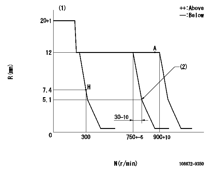
N:Pump speed
R:Rack position (mm)
(1)Target notch: K
(2)Idle sub spring setting: L1.
----------
K=(12) RAL=5.1-0.5mm
----------
----------
K=(12) RAL=5.1-0.5mm
----------
Speed control lever angle

F:Full speed
I:Idle
----------
----------
a=(16deg)+-5deg b=(33deg)+-5deg
----------
----------
a=(16deg)+-5deg b=(33deg)+-5deg
Stop lever angle

N:Pump normal
S:Stop the pump.
----------
----------
a=19deg+-5deg b=53deg+-5deg
----------
----------
a=19deg+-5deg b=53deg+-5deg
Timing setting

(1)Pump vertical direction
(2)Coupling's key groove position at No 1 cylinder's beginning of injection
(3)-
(4)-
----------
----------
a=(10deg)
----------
----------
a=(10deg)
Information:
Problem
The 9Y3222 Injector Rocker Arms may fail on certain 205B, 206B, 211B, 212B, 213B, 214B, 224B, and 325 Excavators; D20D and D250D Articulated Trucks; 446 Backhoe Loaders; 950F Loaders; 3114 Industrial Engines; 3116 Industrial Engines; 3116 Marine Engines; and 3116 Truck Engines. The arm may fail near the adjusting screw or the insert on the injector end of the arm may break.
Affected Product
Model & Identification Number
205B (5ZF1-91)
206B (9BF1-691)
211B (6XG1-162)
212B (3PJ1-912)
213B (1EJ1-378)
214B (4CF1-517; 9MF1-386)
224B (7WF1-181)
325 (2JK174-254)
D20D (9MG1-46)
D250D (6NG1-35)
446 (6XF1-689)
950F (6YG1-2729; 7ZF1-1045)
3114 (Industrial) (5EF1-974)
3116 (Industrial) (2WG1-2506; 4PG1-847)
3116 (Marine) (4KF1-1154)
3116 (Truck) (2BK10000-14485)
Parts Needed
6 - 9Y3222 Injector Arm AssemblyAction Required
If one 9Y3222 Injector Arm Assembly fails, follow the procedures in the Service Manual and replace all six 9Y3222 Injector Arm Assemblies.
In marine applications where there is more than one engine per vessel, install six new 9Y3222 Injector Arm Assemblies on all engines if there is a 9Y3222 Injector Arm Assembly failure.
Service Claim Allowances
All Affected Product Except Truck Engines
This is a 4-hour job.
Truck Engines
Labor segment for test after repair not allowed for this repair.
Parts Disposition
Handle the parts in accordance with your Warranty Bulletin on warranty parts handling.
Have questions with 106672-9350?
Group cross 106672-9350 ZEXEL
Komatsu
Kubota
Komatsu
Shinko-Engin.
106672-9350
9 400 617 161
150095440
INJECTION-PUMP ASSEMBLY
S615
S615