Information injection-pump assembly
BOSCH
9 400 617 158
9400617158
ZEXEL
106672-9320
1066729320
KUBOTA
1212617200
1212617200

Rating:
Service parts 106672-9320 INJECTION-PUMP ASSEMBLY:
1.
_
5.
AUTOM. ADVANCE MECHANIS
7.
COUPLING PLATE
8.
_
9.
_
11.
Nozzle and Holder
12.
Open Pre:MPa(Kqf/cm2)
25.5(260)
15.
NOZZLE SET
Include in #1:
106672-9320
as INJECTION-PUMP ASSEMBLY
Cross reference number
BOSCH
9 400 617 158
9400617158
ZEXEL
106672-9320
1066729320
KUBOTA
1212617200
1212617200
Zexel num
Bosch num
Firm num
Name
106672-9320
9 400 617 158
1212617200 KUBOTA
INJECTION-PUMP ASSEMBLY
LH50 * K 14CA INJECTION PUMP ASSY PE6P,6PD PE
LH50 * K 14CA INJECTION PUMP ASSY PE6P,6PD PE
Calibration Data:
Adjustment conditions
Test oil
1404 Test oil ISO4113 or {SAEJ967d}
1404 Test oil ISO4113 or {SAEJ967d}
Test oil temperature
degC
40
40
45
Nozzle and nozzle holder
105780-8140
Bosch type code
EF8511/9A
Nozzle
105780-0000
Bosch type code
DN12SD12T
Nozzle holder
105780-2080
Bosch type code
EF8511/9
Opening pressure
MPa
17.2
Opening pressure
kgf/cm2
175
Injection pipe
Outer diameter - inner diameter - length (mm) mm 8-3-600
Outer diameter - inner diameter - length (mm) mm 8-3-600
Overflow valve
132424-0620
Overflow valve opening pressure
kPa
157
123
191
Overflow valve opening pressure
kgf/cm2
1.6
1.25
1.95
Tester oil delivery pressure
kPa
157
157
157
Tester oil delivery pressure
kgf/cm2
1.6
1.6
1.6
Direction of rotation (viewed from drive side)
Right R
Right R
Injection timing adjustment
Direction of rotation (viewed from drive side)
Right R
Right R
Injection order
1-5-3-6-
2-4
Pre-stroke
mm
3
2.95
3.05
Beginning of injection position
Drive side NO.1
Drive side NO.1
Difference between angles 1
Cal 1-5 deg. 60 59.5 60.5
Cal 1-5 deg. 60 59.5 60.5
Difference between angles 2
Cal 1-3 deg. 120 119.5 120.5
Cal 1-3 deg. 120 119.5 120.5
Difference between angles 3
Cal 1-6 deg. 180 179.5 180.5
Cal 1-6 deg. 180 179.5 180.5
Difference between angles 4
Cyl.1-2 deg. 240 239.5 240.5
Cyl.1-2 deg. 240 239.5 240.5
Difference between angles 5
Cal 1-4 deg. 300 299.5 300.5
Cal 1-4 deg. 300 299.5 300.5
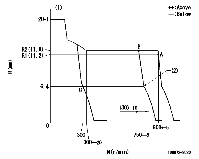
Injection quantity adjustment
Adjusting point
A
Rack position
R1(11.2)
Pump speed
r/min
900
900
900
Average injection quantity
mm3/st.
178.5
174
183
Basic
*
Fixing the rack
*
Injection quantity adjustment_02
Adjusting point
B
Rack position
R2(11.8)
Pump speed
r/min
750
750
750
Average injection quantity
mm3/st.
195
190.5
199.5
Fixing the lever
*
Injection quantity adjustment_03
Adjusting point
C
Rack position
6.4+-0.5
Pump speed
r/min
300
300
300
Average injection quantity
mm3/st.
27
24
30
Fixing the rack
*
Test data Ex:
Governor adjustment
N:Pump speed
R:Rack position (mm)
(1)Notch fixed: K
(2)Idle sub spring setting: L1.
----------
K=5 L1=6.4-0.5mm
----------
----------
K=5 L1=6.4-0.5mm
----------
Speed control lever angle
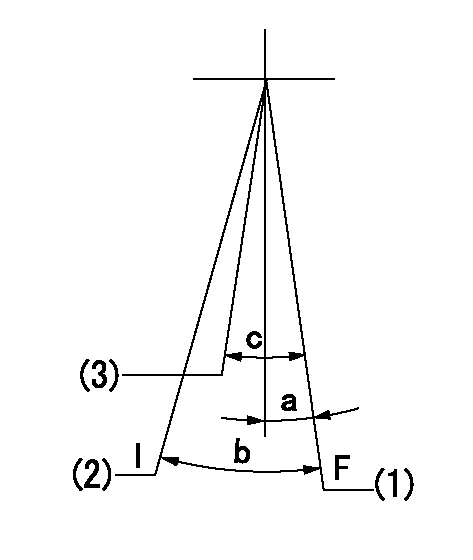
F:Full speed
I:Idle
(1)Speed set at aa (setting at shipping)
(2)Stopper bolt setting
(3)Set the pump speed at bb.
----------
aa=900r/min bb=750r/min
----------
a=(4deg)+-5deg b=(27deg)+-5deg c=(7deg)+-5deg
----------
aa=900r/min bb=750r/min
----------
a=(4deg)+-5deg b=(27deg)+-5deg c=(7deg)+-5deg
Stop lever angle

N:Pump normal
S:Stop the pump.
----------
----------
a=0deg+-5deg b=53deg+-5deg
----------
----------
a=0deg+-5deg b=53deg+-5deg
Timing setting

(1)Pump vertical direction
(2)Coupling's key groove position at No 1 cylinder's beginning of injection
(3)-
(4)-
----------
----------
a=(40deg)
----------
----------
a=(40deg)
Information:
Problem
The retainer clips for the fuel injectors may crack or break on certain Challenger 75 Tractors. Also, the unit injector rocker arms may crack.
Affected Product
Mode & Identification Number
CH75 (4CJ1-308, 4CJ311-317, 4CJ320-331, 4CJ350, 4CJ356,4CJ375-378, 4CJ380, 4CJ382, 4CJ383, 4CJ386, 4CJ391, 4CJ394, 4CJ396, 4CJ406)
Parts Needed
6 - 7E8872 Rocker Arm Assembly (Use as needed)6 - 6I2538 Clip6 - 0R3398 Injector Group (Use as needed)Action Required
See attached rework procedure.
Service Claim Allowances
If required, add the following:
0.5 Hr R&I first fuel injector0.4 Hr R&I each additional fuel injectorParts Disposition
Handle the parts in accordance with your Warranty Bulletin on warranty parts handling.
Attach.
(1-Rework Procedure)Rework Procedure
1. Check for 3X stamped on the block next to the serial number plate. If the block has been stamped do not proceed with the rework unless suspect injectors have recently been installed in that engine. Check SIMS history to be sure.2. Remove hood from over engine, valve covers, and rocker arm stands.3. Inspect the injector rocker arms for the heat code and die code as shown in Illustration 1. Replace any injector rocker arms that have both heat code "1" and die code "1*C" (* Note symbol in Illustration.)
Illustration 1 - Injector Rocker Arm Identification Injector rocker arms must have BOTH heat code "1" and die code "1*C" to be eligible for replacement.
4. Inspect unit injectors for a paint strip across the top face of the spring retainer (either yellow or red). A paint stripe indicates the unit injector has been reworked previously.5. Remove the return to tank fuel line at the fuel manifold adapter (siphon break) and install a 0-100 psi gauge at the manifold.6. Use an O-ring pick to remove the O-ring from the spring retainer of each injector to be reworked. Remove the rocker arm thrust pad from each injector.7. Pressurize fuel system using the priming pump to 30 psi and maintain pressure from 15-30 psi during rework (fuel pressure keeps the injector plunger extended during clip replacement).8. Inspect the 9U5300 Unit Injector Spring Compressor Group. See Illustration 2. The 9U5320 Fixture is for off engine use only.
Illustration 2 - 9U5300 Unit Injector Spring Compressor GroupInstall the compressor group into a rocker arm support bolt hole with the arm aligned over a unit injector spring. Be sure the 5P0541 Nut is backed off to the top of the 9U5321 Tube before tightening the 7X0909 Bolt.
Install the compressor at hole locations closest to the inlet valves.Tighten the 5P0541 Nut to compress the injector spring only enough to allow removal of the clip (the clip is like a valve keeper).
9. Use a small magnet (pencil size works best) and a suitable clip removal tool to remove the old clip from the injector. Do not release tension on the spring until a new clip is installed. Releasing tension before a new clip is installed will cause the injector will come apart. See Illustration 3.
Illustration 3 - Use caution when handling injectors with missing clips. Loose springs and retainers will allow ball to come loose and fall into the engine.10. Inspect the clip
Have questions with 106672-9320?
Group cross 106672-9320 ZEXEL
Komatsu
Kubota
106672-9320
9 400 617 158
1212617200
INJECTION-PUMP ASSEMBLY
LH50
LH50