Information injection-pump assembly
BOSCH
F 01G 09U 08D
f01g09u08d
ZEXEL
106672-3603
1066723603
HINO
220007102A
220007102a
Rating:
Service parts 106672-3603 INJECTION-PUMP ASSEMBLY:
1.
_
5.
AUTOM. ADVANCE MECHANIS
9.
_
11.
Nozzle and Holder
23600-2221A
12.
Open Pre:MPa(Kqf/cm2)
14.7{150}/21.6{220}
14.
NOZZLE
Include in #1:
106672-3603
as INJECTION-PUMP ASSEMBLY
Cross reference number
BOSCH
F 01G 09U 08D
f01g09u08d
ZEXEL
106672-3603
1066723603
HINO
220007102A
220007102a
Zexel num
Bosch num
Firm num
Name
Calibration Data:
Adjustment conditions
Test oil
1404 Test oil ISO4113 or {SAEJ967d}
1404 Test oil ISO4113 or {SAEJ967d}
Test oil temperature
degC
40
40
45
Nozzle and nozzle holder
105780-8140
Bosch type code
EF8511/9A
Nozzle
105780-0000
Bosch type code
DN12SD12T
Nozzle holder
105780-2080
Bosch type code
EF8511/9
Opening pressure
MPa
17.2
Opening pressure
kgf/cm2
175
Injection pipe
Outer diameter - inner diameter - length (mm) mm 8-3-600
Outer diameter - inner diameter - length (mm) mm 8-3-600
Overflow valve
134424-1420
Overflow valve opening pressure
kPa
162
147
177
Overflow valve opening pressure
kgf/cm2
1.65
1.5
1.8
Tester oil delivery pressure
kPa
157
157
157
Tester oil delivery pressure
kgf/cm2
1.6
1.6
1.6
PS/ACT control unit part no.
407980-2
24*
Digi switch no.
21
Direction of rotation (viewed from drive side)
Left L
Left L
Injection timing adjustment
Direction of rotation (viewed from drive side)
Left L
Left L
Injection order
1-4-2-6-
3-5
Pre-stroke
mm
6.4
6.37
6.43
Beginning of injection position
Drive side NO.1
Drive side NO.1
Difference between angles 1
Cal 1-4 deg. 60 59.75 60.25
Cal 1-4 deg. 60 59.75 60.25
Difference between angles 2
Cyl.1-2 deg. 120 119.75 120.25
Cyl.1-2 deg. 120 119.75 120.25
Difference between angles 3
Cal 1-6 deg. 180 179.75 180.25
Cal 1-6 deg. 180 179.75 180.25
Difference between angles 4
Cal 1-3 deg. 240 239.75 240.25
Cal 1-3 deg. 240 239.75 240.25
Difference between angles 5
Cal 1-5 deg. 300 299.75 300.25
Cal 1-5 deg. 300 299.75 300.25
Injection quantity adjustment
Adjusting point
A
Rack position
8.6
Pump speed
r/min
500
500
500
Average injection quantity
mm3/st.
137.4
134.4
140.4
Fixing the lever
*
PS407980-224*
V
V1+0.05+
-0.01
PS407980-224*
mm
6.3+-0.0
3
Remarks
Refer to items regarding the pre-stroke actuator
Refer to items regarding the pre-stroke actuator
Injection quantity adjustment_02
Adjusting point
B
Rack position
9.2
Pump speed
r/min
700
700
700
Average injection quantity
mm3/st.
148.8
146.8
150.8
Max. variation between cylinders
%
0
-2
2
Basic
*
Fixing the lever
*
PS407980-224*
V
V1+0.05+
-0.01
PS407980-224*
mm
6.3+-0.0
3
Injection quantity adjustment_03
Adjusting point
D
Rack position
9.5
Pump speed
r/min
1075
1075
1075
Average injection quantity
mm3/st.
160.2
157.2
163.2
Fixing the lever
*
PS407980-224*
V
V1+0.05+
-0.01
PS407980-224*
mm
6.3+-0.0
3
Injection quantity adjustment_04
Adjusting point
-
Rack position
5.3+-0.5
Pump speed
r/min
225
225
225
Average injection quantity
mm3/st.
11.8
8.8
14.8
Max. variation between cylinders
%
0
-15
15
Fixing the rack
*
PS407980-224*
V
V1+0.05+
-0.01
PS407980-224*
mm
6.3+-0.0
3
Remarks
Adjust only variation between cylinders; adjust governor according to governor specifications.
Adjust only variation between cylinders; adjust governor according to governor specifications.
Injection quantity adjustment_05
Adjusting point
F
Rack position
R1(10.1)
+-0.1
Pump speed
r/min
300
300
300
Average injection quantity
mm3/st.
184.5
181.5
187.5
Fixing the lever
*
PS407980-224*
V
V1+0.05+
-0.01
PS407980-224*
mm
6.3+-0.0
3
Remarks
Startup boost setting
Startup boost setting
0000001601
Pre-stroke
mm
6.4
6.37
6.43
Remarks
When the timing sleeve is pushed up
When the timing sleeve is pushed up
_02
Connector angle
deg.
5
4.5
5.5
Remarks
When the eccentric pin is tightened
When the eccentric pin is tightened
_03
Supply voltage
V
24
23.5
24.5
Ambient temperature
degC
23
18
28
Pre-stroke
mm
4
3.95
4.05
Output voltage
V
2.62
2.61
2.63
Adjustment
*
_04
Supply voltage
V
24
23.5
24.5
Ambient temperature
degC
23
18
28
Pre-stroke
mm
6.4
6.37
6.43
Output voltage
V
1.2
1
1.4
Confirmation
*
Remarks
Output voltage V1
Output voltage V1
_05
Supply voltage
V
24
23.5
24.5
Ambient temperature
degC
23
18
28
Pre-stroke
mm
3.4
Output voltage
V
3
2.98
3
Confirmation
*
_06
Supply voltage
V
24
23.5
24.5
Ambient temperature
degC
23
18
28
Output voltage
V
3.05
3.05
Confirmation of operating range
*
Test data Ex:
Governor adjustment
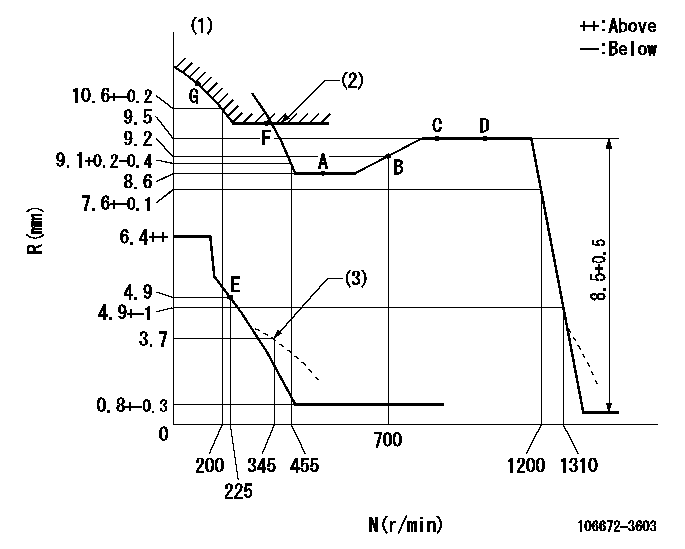
N:Pump speed
R:Rack position (mm)
(1)Tolerance for racks not indicated: +-0.05mm.
(2)Excess fuel setting for starting: SXL (N = N1)
(3)Damper spring setting
----------
SXL=(10.1)+-0.1mm N1=300r/min
----------
----------
SXL=(10.1)+-0.1mm N1=300r/min
----------
Speed control lever angle

F:Full speed
----------
----------
a=18deg+-5deg
----------
----------
a=18deg+-5deg
0000000901

F:Full load
I:Idle
(1)Stopper bolt setting
----------
----------
a=16deg+-5deg b=28.5deg+-3deg
----------
----------
a=16deg+-5deg b=28.5deg+-3deg
Stop lever angle
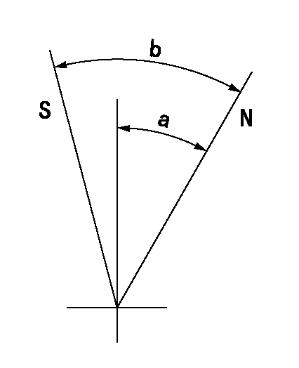
N:Pump normal
S:Stop the pump.
----------
----------
a=40deg+-5deg b=50deg+-5deg
----------
----------
a=40deg+-5deg b=50deg+-5deg
0000001301

(1)Pump vertical direction
(2)Coupling's key groove position at No 1 cylinder's beginning of injection
(3)Pre-stroke: aa
(4)-
----------
aa=6.4+-0.03mm
----------
a=(0deg)
----------
aa=6.4+-0.03mm
----------
a=(0deg)
0000001901

(A): Pre-stroke actuator
(B): Stamp housings A and B at the same time.
(C): Stamping range
1. When installing the pre-stroke actuator on the pump, first tighten the installation bolts loosely, then move the actuator fully clockwise (viewed from the drive side).
Temporary tightening torque: 1 - 1.5 N.m (0.1 - 0.15 kgf.m)
2. Move the actuator in the counterclockwise direction when viewed from the drive side, and adjust so that it becomes the adjustment point of the adjustment value. Then tighten it.
Tightening torque: 7^9 N.m (0.7^0.9 kgf.m)
3. After prestroke actuator installation adjustment, simultaneously stamp both the actuator side and housing side.
----------
----------
----------
----------
0000002201 RACK SENSOR

(VR) measurement voltage
(I) Part number of the control unit
(G) Apply red paint.
(H): End surface of the pump
1. Rack sensor adjustment (-0620)
(1)Fix the speed control lever at the full position
(2)Set the speed to N1 r/min.
(If the boost compensator is provided, apply boost pressure.)
(3)Adjust the bobbin (A) so that the rack sensor's output voltage is VR+-0.01.
(4)At that time, rack position must be Ra.
(5)Apply G at two places.
Connecting part between the joint (B) and the nut (F)
Connecting part between the joint (B) and the end surface of the pump (H)
----------
N1=1000r/min Ra=(9.5)mm
----------
----------
N1=1000r/min Ra=(9.5)mm
----------
0000002301 GOVERNOR TORQUE CONTROL
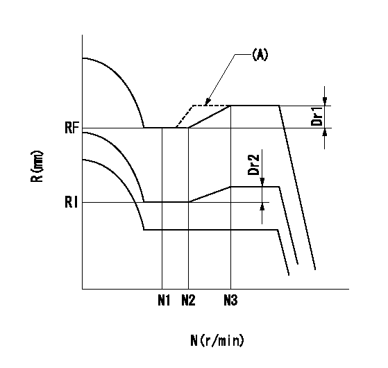
Dr:Torque control stroke
(A): Without torque control spring capsule
1. Adjustment procedures
(1)Procedure is the same as that for the RFD (former type), except that the positive torque control stroke must be determined at the full lever setting.
2. Procedures for adjustment
(1)Remove the torque control spring capsule.
(2)Operate the pump at approximately N1. (End of idling spring operation < N1.)
(3)Tilt the lever to the full side.
(4)Set so that R = RF.
(5)Increase the speed by pushing in the screw (attached to the bracket on the rear of the tension lever) through the adjusting window.
(6)Adjust so that the torque control stroke Dr1 can be obtained.
(7)Align N2 and N3 with the torque control spring capsule.
3. Final confirmation
(1)After final confirmation, temporarily set the load lever to N = N1, R = idling position.
(2)From this condition, increase speed to N = N4.
(3)Confirm that positive torque control stroke is Dr2.
----------
N1=500r/min N2=- N3=- N4=1000r/min RF=8.6mm RI=4.9mm Dr1=0.9mm Dr2=0+0.3mm
----------
----------
N1=500r/min N2=- N3=- N4=1000r/min RF=8.6mm RI=4.9mm Dr1=0.9mm Dr2=0+0.3mm
----------
Information:
Changing Filter Element
A 1U-9578 Repair Kit (Nozzle Tester) is available to maintain the tester. The repair kit contains a new filter along with seals, gaskets, and instructions on how to use the kit. Do not reuse seals and gaskets when changing the filter. Always use new seals and gaskets.Calibration Fluid
The calibration fluid should be changed every three months or after testing 50 nozzles. The fluid should also be changed whenever inaccurate test results are suspected.Inaccurate test results can be caused by fluid with improper specific gravity, viscosity, visible contamination, fluid that foams, or discolored fluid.The fluid should also be checked for the correct viscosity. It is a good practice to test new calibration fluid for the correct viscosity and specific gravity. Use a 9U-7840 Test Kit to check calibration fluid.
Do not refill the nozzle tester with test oil that has been pumped through a fuel injection nozzle. Nozzles contain residual amounts of diesel fuel that is pumped out when tested. The diesel fuel mixes with and contaminates the test oil. Using this diesel fuel test oil combination will damage the nozzle tester.
9U-7840 Test Kit For Checking Fluid Viscosity Calibration fluid will last longer if the nozzles are cleaned prior to testing. As the fluid in the tester becomes contaminated, the accuracy of the test results are decreased.Changing Calibration Fluid
1. Completely drain the reservoir and any fluid contained in the pump mechanism. Special care must be taken for the disposal of the calibration fluid. Recent regulations prohibit the dumping of oil; all oil must be properly disposed.2. Thoroughly clean the reservoir using an 8T-9011 Component Cleaner or equivalent and clean towels.3. Install a new 8T-5313 Filter Element (10 micron). A new filter element should be installed whenever the calibration fluid is changed (even if less than 3 months).4. Fill the reservoir with clean calibration fluid (refer to the chart for part numbers).Nozzle Tester Pressure Gauges
Pressure gauges in the nozzle tester should be checked for accuracy every 12 months or whenever inaccurate test results are suspected. Gauges should also be checked whenever a gauge is damaged or the needle does not return to zero. Record all data on the data sheets in the "Forms" section.1. Remove pressure gauge from the nozzle tester.2. Install gauge adapter from 5P-8558 Calibrating Group Pressure Gauge onto pressure gauge.3. Connect pressure to tester port.4. Use a 1U-5230 Hand Pump to apply pressure to the gauge. Increase the pressure to 25% of the pressure gauges capacity.5. Check the actual gauge pressure with the tester gauge reading. The two pressures should be within two percent of each other.6. Repeat Step 5 at 50, 75 and 100 percent increments. Each increment should be within two percent of the tester gauge reading.7. If the pressure is not within two percent, the pressure gauge should be replaced.Check Tester For Leakage
Before testing any nozzle, check the tester for obvious external leakage. Leakage in the tester will give inaccurate test results, causing good nozzles to be rejected.Always check the tester for leakage