Information injection-pump assembly
ZEXEL
106672-3471
1066723471
HINO
220006501A
220006501a
Rating:
Cross reference number
ZEXEL
106672-3471
1066723471
HINO
220006501A
220006501a
Zexel num
Bosch num
Firm num
Name
Calibration Data:
Adjustment conditions
Test oil
1404 Test oil ISO4113 or {SAEJ967d}
1404 Test oil ISO4113 or {SAEJ967d}
Test oil temperature
degC
40
40
45
Nozzle and nozzle holder
105780-8140
Bosch type code
EF8511/9A
Nozzle
105780-0000
Bosch type code
DN12SD12T
Nozzle holder
105780-2080
Bosch type code
EF8511/9
Opening pressure
MPa
17.2
Opening pressure
kgf/cm2
175
Injection pipe
Outer diameter - inner diameter - length (mm) mm 8-3-600
Outer diameter - inner diameter - length (mm) mm 8-3-600
Overflow valve
134424-1520
Overflow valve opening pressure
kPa
162
147
177
Overflow valve opening pressure
kgf/cm2
1.65
1.5
1.8
Tester oil delivery pressure
kPa
157
157
157
Tester oil delivery pressure
kgf/cm2
1.6
1.6
1.6
PS/ACT control unit part no.
407980-2
24*
Digi switch no.
21
Direction of rotation (viewed from drive side)
Right R
Right R
Injection timing adjustment
Direction of rotation (viewed from drive side)
Right R
Right R
Injection order
1-4-2-6-
3-5
Pre-stroke
mm
6.4
6.37
6.43
Beginning of injection position
Drive side NO.1
Drive side NO.1
Difference between angles 1
Cal 1-4 deg. 60 59.75 60.25
Cal 1-4 deg. 60 59.75 60.25
Difference between angles 2
Cyl.1-2 deg. 120 119.75 120.25
Cyl.1-2 deg. 120 119.75 120.25
Difference between angles 3
Cal 1-6 deg. 180 179.75 180.25
Cal 1-6 deg. 180 179.75 180.25
Difference between angles 4
Cal 1-3 deg. 240 239.75 240.25
Cal 1-3 deg. 240 239.75 240.25
Difference between angles 5
Cal 1-5 deg. 300 299.75 300.25
Cal 1-5 deg. 300 299.75 300.25
Injection quantity adjustment
Adjusting point
A
Rack position
9.3
Pump speed
r/min
700
700
700
Average injection quantity
mm3/st.
149.4
147.4
151.4
Max. variation between cylinders
%
0
-2
2
Basic
*
Fixing the lever
*
Boost pressure
kPa
38.7
38.7
Boost pressure
mmHg
290
290
PS407980-224*
V
V1+0.05+
-0.01
PS407980-224*
mm
6.3+-0.0
3
Remarks
Refer to items regarding the pre-stroke actuator
Refer to items regarding the pre-stroke actuator
Injection quantity adjustment_02
Adjusting point
D
Rack position
9.4
Pump speed
r/min
1075
1075
1075
Average injection quantity
mm3/st.
145.5
142.5
148.5
Max. variation between cylinders
%
0
-5
5
Fixing the lever
*
Boost pressure
kPa
38.7
38.7
Boost pressure
mmHg
290
290
PS407980-224*
V
V1+0.05+
-0.01
PS407980-224*
mm
6.3+-0.0
3
Injection quantity adjustment_03
Adjusting point
F
Rack position
5+-0.5
Pump speed
r/min
225
225
225
Average injection quantity
mm3/st.
11
8
14
Max. variation between cylinders
%
0
-15
15
Fixing the rack
*
Boost pressure
kPa
0
0
0
Boost pressure
mmHg
0
0
0
PS407980-224*
V
V1+0.05+
-0.01
PS407980-224*
mm
6.3+-0.0
3
Injection quantity adjustment_04
Adjusting point
G
Rack position
7.9
Pump speed
r/min
400
400
400
Average injection quantity
mm3/st.
112
110
114
Fixing the lever
*
Boost pressure
kPa
0
0
0
Boost pressure
mmHg
0
0
0
PS407980-224*
V
V1+0.05+
-0.01
PS407980-224*
mm
6.3+-0.0
3
Injection quantity adjustment_05
Adjusting point
H
Rack position
-
Pump speed
r/min
100
100
100
Average injection quantity
mm3/st.
128
128
Fixing the lever
*
Boost pressure
kPa
0
0
0
Boost pressure
mmHg
0
0
0
PS407980-224*
V
V1+0.05+
-0.01
PS407980-224*
mm
6.3+-0.0
3
Injection quantity adjustment_06
Adjusting point
I
Rack position
-
Pump speed
r/min
300
300
300
Average injection quantity
mm3/st.
170
165
175
Fixing the lever
*
Boost pressure
kPa
0
0
0
Boost pressure
mmHg
0
0
0
Rack limit
*
PS407980-224*
V
V1+0.05+
-0.01
PS407980-224*
mm
6.3+-0.0
3
Remarks
Confirm point D after setting point I..
Confirm point D after setting point I..
Boost compensator adjustment
Pump speed
r/min
500
500
500
Rack position
7.9
Boost pressure
kPa
9.3
7.3
9.3
Boost pressure
mmHg
70
55
70
Boost compensator adjustment_02
Pump speed
r/min
500
500
500
Rack position
9.3
Boost pressure
kPa
25.3
25.3
25.3
Boost pressure
mmHg
190
190
190
0000001601
Pre-stroke
mm
6.4
6.37
6.43
Remarks
When the timing sleeve is pushed up
When the timing sleeve is pushed up
_02
Connector angle
deg.
5
4.5
5.5
Remarks
When the eccentric pin is tightened
When the eccentric pin is tightened
_03
Supply voltage
V
24
23.5
24.5
Ambient temperature
degC
23
18
28
Pre-stroke
mm
4
3.95
4.05
Output voltage
V
2.62
2.61
2.63
Adjustment
*
_04
Supply voltage
V
24
23.5
24.5
Ambient temperature
degC
23
18
28
Pre-stroke
mm
6.4
6.37
6.43
Output voltage
V
1.2
1
1.4
Confirmation
*
Remarks
Output voltage V1
Output voltage V1
_05
Supply voltage
V
24
23.5
24.5
Ambient temperature
degC
23
18
28
Pre-stroke
mm
3.4
Output voltage
V
3
2.98
3
Confirmation
*
_06
Supply voltage
V
24
23.5
24.5
Ambient temperature
degC
23
18
28
Output voltage
V
3.05
3.05
Confirmation of operating range
*
Test data Ex:
Governor adjustment
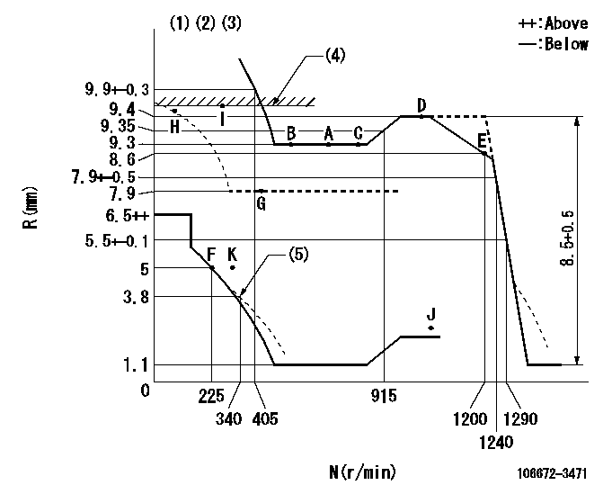
N:Pump speed
R:Rack position (mm)
(1)Lever ratio: RT
(2)Target shim dimension: TH
(3)Tolerance for racks not indicated: +-0.05mm.
(4)RACK LIMIT
(5)Damper spring setting
----------
RT=1 TH=2mm
----------
----------
RT=1 TH=2mm
----------
Speed control lever angle

F:Full speed
----------
----------
a=13deg+-5deg
----------
----------
a=13deg+-5deg
0000000901
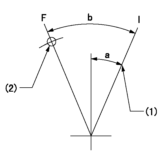
F:Full load
I:Idle
(1)Stopper bolt setting
(2)Use the hole at R = aa
----------
aa=69mm
----------
a=25deg+-5deg b=30deg+-3deg
----------
aa=69mm
----------
a=25deg+-5deg b=30deg+-3deg
Stop lever angle

N:Pump normal
S:Stop the pump.
----------
----------
a=40deg+-5deg b=50deg+-5deg
----------
----------
a=40deg+-5deg b=50deg+-5deg
0000001301

(1)Pump vertical direction
(2)Coupling's key groove position at No 1 cylinder's beginning of injection
(3)Pre-stroke: aa
(4)-
----------
aa=6.4+-0.03mm
----------
a=(40deg)
----------
aa=6.4+-0.03mm
----------
a=(40deg)
0000001901

(A): Pre-stroke actuator
(B): Stamp housings A and B at the same time.
(C): Stamping range
1. When installing the pre-stroke actuator on the pump, first tighten the installation bolts loosely, then move the actuator fully clockwise (viewed from the drive side).
Temporary tightening torque: 1 - 1.5 N.m (0.1 - 0.15 kgf.m)
2. Move the actuator in the counterclockwise direction when viewed from the drive side, and adjust so that it becomes the adjustment point of the adjustment value. Then tighten it.
Tightening torque: 7^9 N.m (0.7^0.9 kgf.m)
3. After prestroke actuator installation adjustment, simultaneously stamp both the actuator side and housing side.
----------
----------
----------
----------
0000002201 RACK SENSOR
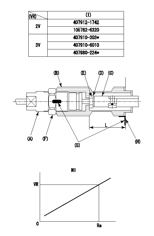
(VR) measurement voltage
(I) Part number of the control unit
(G) Apply red paint.
(H): End surface of the pump
Adjustment of the rack sensor (-0720)
1. Rack limit adjustment
(1)After mounting the joint (B), select the shim (D) so that the rack position is in the rack limit position.
(2)Install the rod (E) to the block (C).
(3)At the rack limit, set the distance between the pump end face and the rod (E) to L1.
2. Rack sensor
(1)Screw in the bobbin (A) until it contacts the joint (B).
(2)Fix the speed control lever at the full side and set the pump speed at N1.
(3)Adjust the depth that the bobbin (A) is screwed in so that the control unit's rack sensor output voltage is VR+-0.01 (V), then tighten the nut (F). (If equipped with a boost compensator, perform with boost pressure applied.)
(4)Apply red paint to both the joint (B) and the nut (F) join, and the joint (B) and the pump join. Output voltage VR +-0.01(V), speed N1, rack position Ra, rack sensor supply voltage 5+-0.01 (V)
----------
L=33.5+-0.1 mm N1=550r/min Ra=9.3mm
----------
----------
L=33.5+-0.1 mm N1=550r/min Ra=9.3mm
----------
Information:
When fuel has stopped flowing out, turn the crankshaft slightly in the reverse direction such that fuel flows out. Then, slowly turn the crankshaft clockwise again to more accurately verify the point at which fuel stops flowing out.
End of fuel flow(c) If the IT mark on the crankshaft pulley and the mark on the gear case are aligned when fuel stops flowing out the injection timing is normal.
Timing marks(3) Adjustment
(a) If the injection timing is out of specification, make adjustments by increasing or decreasing the thickness of the injection pump's mounting shim. A change of 0.1 mm in the shim thickness yields a change of approximately 1° in the injection timing.
Injection timing adjusting shim(b) Increasing the shim thickness retards the injection timing, and decreasing the shim thickness advances it. Shims come in 9 different thicknesses from 0.2 mm (0.008 in.) to 1.0 mm (0.039 in.) at intervals of 0.1 mm (0.004 in.). The thickness is not indicated on the shim, so any shim should be measured with a vernier caliper before being used.
Before using any shim, apply sealant to both sides to prevent oil leakage.
(c) After making adjustments, check the injection timing is correct.(d) Close the cock on the fuel filter, then fit the delivery valve spring and injection pipe in their original positions.
Adjusting injection timingAdjusting Idle Speed
(1) Preparation for Adjustment
(a) Warm up the engine unit the coolant reaches a temperature of 60°C (140°F) or higher.(b) Make sure the valve clearances, injection timing, and injectors are normal.(2) Adjusting Low-Idle Speed
Loosen the locknut on the idling set bolt, turn the bolt to achieve the specified low-idle speed (1000 25min-1), then tighten the lock nut to hold the bolt in that position.(3) Adjusting No-Load Maximum Speed
Loosen the lock nut on the high-speed set bolt, turn the bolt to achieve the specified no-load maximum speed (2600 +30-10 min-1), then tighten the lock nut to hold the bolt in that position.
Adjusting idle speedAdjusting Fan Belt Tension
(1) Press the fan belt with the specified force mid-way between the alternator pulley and crankshaft pulley, and observe the extent of deflection.Unit: mm (in.) (2) If the extent of deflection is out of specification, loosen the adjusting bolt and adjust the fan belt tension by moving the alternator. Retighten the adjusting bolt securely.
Adjusting fan belt tensionRunning in the Engine
After an overhaul, the engine should be tested and inspected on a dynamometer. This operation serves to run in the engine's major moving parts.Starting the Engine
(1) Before starting the engine, check the coolant, engine oil and fuel levels and bleed all air out of the fuel and cooling systems.(2) Without supplying fuel to the engine, crank the engine for about 10 seconds to permit oil to circulate through it.(3) Move the speed control lever slightly in the fuel-increase direction. (Do not move the lever to the full-injection position.) Then, turn the starter switch to the START position to start the engine.(4) Once the engine has started, set it to the low-idle speed using the speed control lever.Inspection after