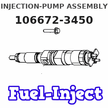
Information injection-pump assembly
ZEXEL
106672-3450
1066723450
HINO
220203490A
220203490a
Rating:
Cross reference number
ZEXEL
106672-3450
1066723450
HINO
220203490A
220203490a
Zexel num
Bosch num
Firm num
Name
Calibration Data:
Adjustment conditions
Test oil
1404 Test oil ISO4113 or {SAEJ967d}
1404 Test oil ISO4113 or {SAEJ967d}
Test oil temperature
degC
40
40
45
Nozzle and nozzle holder
105780-8140
Bosch type code
EF8511/9A
Nozzle
105780-0000
Bosch type code
DN12SD12T
Nozzle holder
105780-2080
Bosch type code
EF8511/9
Opening pressure
MPa
17.2
Opening pressure
kgf/cm2
175
Injection pipe
Outer diameter - inner diameter - length (mm) mm 8-3-600
Outer diameter - inner diameter - length (mm) mm 8-3-600
Overflow valve
134424-0920
Overflow valve opening pressure
kPa
162
147
177
Overflow valve opening pressure
kgf/cm2
1.65
1.5
1.8
Tester oil delivery pressure
kPa
157
157
157
Tester oil delivery pressure
kgf/cm2
1.6
1.6
1.6
Direction of rotation (viewed from drive side)
Left L
Left L
Injection timing adjustment
Direction of rotation (viewed from drive side)
Left L
Left L
Injection order
1-4-2-6-
3-5
Pre-stroke
mm
3.3
3.2
3.3
Beginning of injection position
Drive side NO.1
Drive side NO.1
Difference between angles 1
Cal 1-4 deg. 60 59.5 60.5
Cal 1-4 deg. 60 59.5 60.5
Difference between angles 2
Cyl.1-2 deg. 120 119.5 120.5
Cyl.1-2 deg. 120 119.5 120.5
Difference between angles 3
Cal 1-6 deg. 180 179.5 180.5
Cal 1-6 deg. 180 179.5 180.5
Difference between angles 4
Cal 1-3 deg. 240 239.5 240.5
Cal 1-3 deg. 240 239.5 240.5
Difference between angles 5
Cal 1-5 deg. 300 299.5 300.5
Cal 1-5 deg. 300 299.5 300.5
Injection quantity adjustment
Adjusting point
A
Rack position
8.3
Pump speed
r/min
900
900
900
Average injection quantity
mm3/st.
128.7
125.7
131.7
Max. variation between cylinders
%
0
-4
4
Fixing the rack
*
Injection quantity adjustment_02
Adjusting point
B
Rack position
8.7
Pump speed
r/min
750
750
750
Average injection quantity
mm3/st.
148.9
146.9
150.9
Max. variation between cylinders
%
0
-4
4
Basic
*
Fixing the lever
*
Injection quantity adjustment_03
Adjusting point
C
Rack position
5.1+-0.5
Pump speed
r/min
360
360
360
Average injection quantity
mm3/st.
11.2
8.2
14.2
Max. variation between cylinders
%
0
-15
15
Fixing the rack
*
Test data Ex:
Governor adjustment
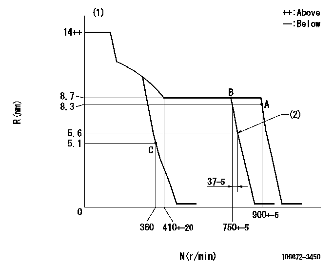
N:Pump speed
R:Rack position (mm)
(1)Target notch: K
(2)Idle sub spring setting: L1.
----------
K=7 L1=5.6-0.5mm
----------
----------
K=7 L1=5.6-0.5mm
----------
Speed control lever angle
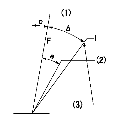
F:Full speed
I:Idle
(1)Speed set at aa (setting at shipping)
(2)Set the pump speed at bb.
(3)Stopper bolt setting
----------
aa=900r/min bb=750r/min
----------
a=4deg+-5deg b=18deg+-5deg c=5deg+-5deg
----------
aa=900r/min bb=750r/min
----------
a=4deg+-5deg b=18deg+-5deg c=5deg+-5deg
Stop lever angle

N:Pump normal
S:Stop the pump.
----------
----------
a=27deg+-5deg b=53deg+-5deg
----------
----------
a=27deg+-5deg b=53deg+-5deg
Timing setting

(1)Pump vertical direction
(2)Coupling's key groove position at No 1 cylinder's beginning of injection
(3)-
(4)-
----------
----------
a=(0deg)
----------
----------
a=(0deg)
Information:
An additional 5 hours is allowed if the harness must replaced.
Product smu/age whichever comes first Caterpillar Dealer Suggested Customer Suggested
Parts % Labor Hrs% Parts % Labor Hrs% Parts % Labor Hrs%
*******Group 2*******
0-4000 hrs,
0-12 mo 100.0% 100.0% 0.0% 0.0% 0.0% 0.0%
This is a 3.0-hour job for Group 2
An additional 10 hours is allowed if the harness must replaced.
PARTS DISPOSITION
Handle the parts in accordance with your Warranty Bulletin on warranty parts handling.
Rework Procedure
Group Number 1
Injector Harness Inspection
-Raise the engine enclosure hood.
-Remove the air intake pipe connecting the air filter to the turbo inlet.
-Remove the valve covers.
-Inspect the injector harness wiring for contact between the harness and valve springs.
Image1.1.1
Repair
-If the harness is close to the valve spring, adjust the harness by disconnecting the injector connector rotating the connector 360 degrees and reconnecting it. This should slightly twist the wires and pull them away from the springs.
Image1.2.1
Injector Harness Replacement (If Necessary)
-If the injector harness has contacted the spring and cut the wire or exposed the wire, then replace the injector harness that is under the valve cover.
-When installing the new harness to the valve cover base make sure the tabs do not turn while torquing down the bolts(see the picture below). Keep the tabs straight, and this will help keep the wiring away from the valve springs.
Image1.3.1
Group Number 2
Injector Harness Inspection
-Remove the rear engine enclosure.
-Remove the clamp for flex boot on the air filter housing.
-Remove the rubber elbow on the inlet of the compressor side of the turbocharger.
-Remove the clamps called out in the photo for the turbocharger outlet pipe that connects to the aftercooler.
Image2.1.1
-Remove all three engine valve covers.
-Inspect the injector harness wiring for contact between the harness and valve springs.
Image2.2.1
Repair
-If the harness is close to the valve spring, adjust the harness by disconnecting the injector connector rotating the connector 360 degrees and reconnecting it. This should slightly twist the wires and pull them away from the springs.
Image2.3.1
Injector Harness Replacement (If Necessary)
-If the injector harness has contacted the spring and cut the wire or exposed the wire, then replace the injector harness that is under the valve cover.
-Remove the doors, hood, Clean Emissions Module (CEM) and mounting plate, and valve cover base.
-When installing the new harness to the valve cover base make sure the tabs do not turn while torquing down the bolts(see the picture below). Keep the tabs straight, and this will help keep the wiring away from the valve springs.
Image2.4.1
-Reinstall the previously removed hardware, and use the new 344-8311 exhaust clamp.
Image2.5.1