Information injection-pump assembly
ZEXEL
106672-3441
1066723441
HINO
220202881A
220202881a

Rating:
Service parts 106672-3441 INJECTION-PUMP ASSEMBLY:
1.
_
5.
AUTOM. ADVANCE MECHANIS
8.
_
9.
_
11.
Nozzle and Holder
23600-1860D
12.
Open Pre:MPa(Kqf/cm2)
21.6{220}
15.
NOZZLE SET
Include in #1:
106672-3441
as INJECTION-PUMP ASSEMBLY
Cross reference number
ZEXEL
106672-3441
1066723441
HINO
220202881A
220202881a
Zexel num
Bosch num
Firm num
Name
106672-3441
220202881A HINO
INJECTION-PUMP ASSEMBLY
EK130T * K
EK130T * K
Calibration Data:
Adjustment conditions
Test oil
1404 Test oil ISO4113 or {SAEJ967d}
1404 Test oil ISO4113 or {SAEJ967d}
Test oil temperature
degC
40
40
45
Nozzle and nozzle holder
105780-8140
Bosch type code
EF8511/9A
Nozzle
105780-0000
Bosch type code
DN12SD12T
Nozzle holder
105780-2080
Bosch type code
EF8511/9
Opening pressure
MPa
17.2
Opening pressure
kgf/cm2
175
Injection pipe
Outer diameter - inner diameter - length (mm) mm 8-3-600
Outer diameter - inner diameter - length (mm) mm 8-3-600
Overflow valve
134424-0920
Overflow valve opening pressure
kPa
162
147
177
Overflow valve opening pressure
kgf/cm2
1.65
1.5
1.8
Tester oil delivery pressure
kPa
157
157
157
Tester oil delivery pressure
kgf/cm2
1.6
1.6
1.6
Direction of rotation (viewed from drive side)
Left L
Left L
Injection timing adjustment
Direction of rotation (viewed from drive side)
Left L
Left L
Injection order
1-4-2-6-
3-5
Pre-stroke
mm
3.3
3.2
3.3
Beginning of injection position
Drive side NO.1
Drive side NO.1
Difference between angles 1
Cal 1-4 deg. 60 59.5 60.5
Cal 1-4 deg. 60 59.5 60.5
Difference between angles 2
Cyl.1-2 deg. 120 119.5 120.5
Cyl.1-2 deg. 120 119.5 120.5
Difference between angles 3
Cal 1-6 deg. 180 179.5 180.5
Cal 1-6 deg. 180 179.5 180.5
Difference between angles 4
Cal 1-3 deg. 240 239.5 240.5
Cal 1-3 deg. 240 239.5 240.5
Difference between angles 5
Cal 1-5 deg. 300 299.5 300.5
Cal 1-5 deg. 300 299.5 300.5
Injection quantity adjustment
Adjusting point
A
Rack position
8.9
Pump speed
r/min
950
950
950
Average injection quantity
mm3/st.
155.5
153.5
157.5
Max. variation between cylinders
%
0
-4
4
Basic
*
Fixing the lever
*
Injection quantity adjustment_02
Adjusting point
C
Rack position
5.1+-0.5
Pump speed
r/min
360
360
360
Average injection quantity
mm3/st.
11
8
14
Max. variation between cylinders
%
0
-15
15
Fixing the rack
*
Test data Ex:
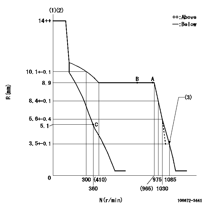
Governor adjustment

N:Pump speed
R:Rack position (mm)
(1)Target notch: K
(2)Tolerance for racks not indicated: +-0.05mm.
(3)Set idle sub-spring
----------
K=17
----------
----------
K=17
----------
Speed control lever angle

F:Full speed
I:Idle
(1)Stopper bolt setting
----------
----------
a=8deg+-5deg b=20deg+-5deg
----------
----------
a=8deg+-5deg b=20deg+-5deg
Stop lever angle

N:Pump normal
S:Stop the pump.
(1)Rack position aa or less, pump speed bb
----------
aa=4.6mm bb=0r/min
----------
a=27deg+-5deg b=53deg+-5deg
----------
aa=4.6mm bb=0r/min
----------
a=27deg+-5deg b=53deg+-5deg
Timing setting

(1)Pump vertical direction
(2)Coupling's key groove position at No 1 cylinder's beginning of injection
(3)-
(4)-
----------
----------
a=(0deg)
----------
----------
a=(0deg)
Information:
1. Disassembly and Assembly of General Parts
1.1 Oil SealsWhen driving oil seals into place, respect the following instructions. Driving Seals into Housing:(a) Orient the seal lip correctly, making sure it is not damaged.(b) Before driving a seal into place, apply a light coat of grease to the periphery of the seal that fits into the housing.(c) Use a driving tool like the one shown in the drawing that is specially designed for the purpose. The tool can properly guide the lip and hold evenly the top of the seal when it is tapped, so it allows the seal to be driven straight down. Do not use hammers on bare seals as seal will be damaged and consequently oil leak will result.
Oil seal driving tool Driving Seals onto Shaft:(a) Coat the seal lip with grease.(b) Use a seal guide like the one shown in the drawing when the shaft has steps, splines, threads or keyways.
Oil seal guide1.2 O-RingsUse a guide when it is necessary to move O-rings over steps, splines, threads or keyways to install them. Apply a light coat of grease to O-rings before fitting them.
O-ring guide1.3 Bearings(1) When driving bearings into place, be sure to tap the race that is being fitted. (If the inner race is being fitted, tap the inner race. Likewise, if it is the outer race that is being fitted, tap the outer race.) Use fitting tools like the one shown in the drawing that are appropriate for inner or outer races.
Bearing fitting tool(2) Bearings are best fitted using a press as shock loads and errors can be minimized.
Fitting bearing using a press1.4 Lock PlatesAlways bend lock plates properly. The drawing on the right shows some of typical lock plates being bent properly and improperly.1.5 Split Pins and Spring PinsAs a rule, all split pins must be replaced with new ones after each removal. It is also important to bend split pins properly. Spring pins must be driven into place completely.
Typical locking plates with good and bad bends
Have questions with 106672-3441?
Group cross 106672-3441 ZEXEL
Hino
Hino
106672-3441
220202881A
INJECTION-PUMP ASSEMBLY
EK130T
EK130T
