Information injection-pump assembly
ZEXEL
106672-3410
1066723410
HINO
220203050A
220203050a
Rating:
Cross reference number
ZEXEL
106672-3410
1066723410
HINO
220203050A
220203050a
Zexel num
Bosch num
Firm num
Name
Calibration Data:
Adjustment conditions
Test oil
1404 Test oil ISO4113 or {SAEJ967d}
1404 Test oil ISO4113 or {SAEJ967d}
Test oil temperature
degC
40
40
45
Nozzle and nozzle holder
105780-8140
Bosch type code
EF8511/9A
Nozzle
105780-0000
Bosch type code
DN12SD12T
Nozzle holder
105780-2080
Bosch type code
EF8511/9
Opening pressure
MPa
17.2
Opening pressure
kgf/cm2
175
Injection pipe
Outer diameter - inner diameter - length (mm) mm 8-3-600
Outer diameter - inner diameter - length (mm) mm 8-3-600
Overflow valve
134424-1420
Overflow valve opening pressure
kPa
162
147
177
Overflow valve opening pressure
kgf/cm2
1.65
1.5
1.8
Tester oil delivery pressure
kPa
157
157
157
Tester oil delivery pressure
kgf/cm2
1.6
1.6
1.6
Direction of rotation (viewed from drive side)
Right R
Right R
Injection timing adjustment
Direction of rotation (viewed from drive side)
Right R
Right R
Injection order
1-4-2-6-
3-5
Pre-stroke
mm
4.5
4.4
4.5
Beginning of injection position
Drive side NO.1
Drive side NO.1
Difference between angles 1
Cal 1-4 deg. 60 59.5 60.5
Cal 1-4 deg. 60 59.5 60.5
Difference between angles 2
Cyl.1-2 deg. 120 119.5 120.5
Cyl.1-2 deg. 120 119.5 120.5
Difference between angles 3
Cal 1-6 deg. 180 179.5 180.5
Cal 1-6 deg. 180 179.5 180.5
Difference between angles 4
Cal 1-3 deg. 240 239.5 240.5
Cal 1-3 deg. 240 239.5 240.5
Difference between angles 5
Cal 1-5 deg. 300 299.5 300.5
Cal 1-5 deg. 300 299.5 300.5
Injection quantity adjustment
Adjusting point
A
Rack position
7.9
Pump speed
r/min
800
800
800
Average injection quantity
mm3/st.
111
109
113
Max. variation between cylinders
%
0
-2
2
Basic
*
Fixing the lever
*
Injection quantity adjustment_02
Adjusting point
B
Rack position
5.1+-0.5
Pump speed
r/min
360
360
360
Average injection quantity
mm3/st.
10
7
13
Max. variation between cylinders
%
0
-15
15
Fixing the rack
*
Injection quantity adjustment_03
Adjusting point
C
Rack position
-
Pump speed
r/min
100
100
100
Average injection quantity
mm3/st.
148.5
143.5
153.5
Fixing the lever
*
Rack limit
*
Test data Ex:
Governor adjustment
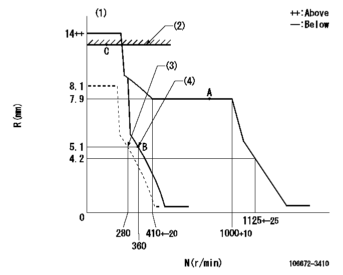
N:Pump speed
R:Rack position (mm)
(1)Target notch: K
(2)RACK LIMIT
(3)Set idle sub-spring
(4)Main spring setting
----------
K=(9)
----------
----------
K=(9)
----------
Speed control lever angle

F:Full speed
I:Idle
S:Stop
----------
----------
a=(2deg)+-5deg b=32deg+-3deg c=(17deg)+-5deg
----------
----------
a=(2deg)+-5deg b=32deg+-3deg c=(17deg)+-5deg
Stop lever angle

N:Pump normal
S:Stop the pump.
----------
----------
a=27deg+-5deg b=53deg+-5deg
----------
----------
a=27deg+-5deg b=53deg+-5deg
0000001501 LEVER
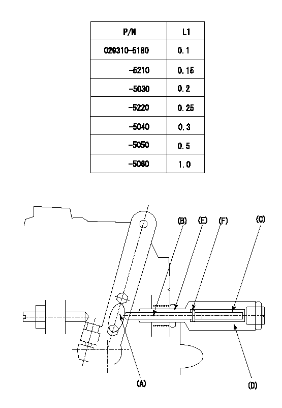
(F) P/N: Part number of the shim
L1:Thickness (mm)
1. Adjustment of the control lever
(1)Perform idling with the control lever (A) contacting the pushrod (B). At this time, confirm that the spring (C) is not compressed by control lever (A)'s operating torque.
(2)To set the stop position, compress spring (C) using the control lever (A) and adjust the rack so that it contacts the guide screw (D) at position L2. Then, set and fix using the lock nut (E). Adjust the rack position L2 at this time using the shim (F).
(3)Confirm that the control lever (A) returns to the idling position when pulled in the stop direction and then released.
----------
L2=0.2~2mm
----------
----------
L2=0.2~2mm
----------
Timing setting

(1)Pump vertical direction
(2)Coupling's key groove position at No 1 cylinder's beginning of injection
(3)-
(4)-
----------
----------
a=(50deg)
----------
----------
a=(50deg)
Information:
2. Removing Accessories
(1) Removing Fan(a) Reduce the tension applied by the tension pulley by pushing the alternator toward the engine, then remove the water pump drive belt (1).(b) Remove the fan mounting bolts (2), then remove the fan (3).(c) Remove the water pump pulley (4), which was previously retained by the fan mounting bolts (2).(2) Removing Thermostat FittingRemove the water outlet fitting (1), then remove the thermostat (2), thermostat fitting (3), water joint (4), and temperature joint (5) in that sequence. (3) Removing Exhaust and Intake Manifolds(a) Remove the exhaust manifold mounting bolts, then remove the exhaust manifold (1) and the gasket (2).(b) Remove the intake manifold mounting bolts, then remove the intake manifold (3) and the gasket (4). When refitting the manifolds, fit each gasket with the side marked "MANIFOLD" facing the manifold. (4) Removing Water PumpRemove the water pump mounting bolts, then remove the water pump (1). (5) Removing Alternator(a) Disconnect the battery cables.(b) Disconnect the lead from terminal B at the rear of the alternator.(c) Remove the alternator connector.(d) Loosen the alternator brace bolt (1) and support bolt (2), then push the alternator toward the engine and remove the fan belt.(e) Remove the alternator. (6) Removing Starter(a) Disconnect the battery's (-) and (+) terminals in that sequence.(b) Disconnect the start wiring (1).(c) Remove the starter's two mounting bolts (2), then remove the starter (3). (7) Removing Oil Filter(a) The oil filter (2) must be replaced every 100 hours of use.(b) Remove the oil filter using a filter wrench (1). (8) Removing Fuel Filter(a) Remove the fuel pipe (1) that leads from the fuel tank and the fuel pipe (2) that leads to the fuel pump.(b) Remove the fuel filter (3) from the engine. (9) Removing Fuel Pipes(a) Remove the clamps from the four fuel pipes (1), then disconnect the fuel pipes from the engine and from the injection pump.(b) Remove the joints and clips from the fuel hose (2), then disconnect the fuel hose from the injector holders.
To keep dirt out of the fuel system, fit rubber caps over the parts of the injection pump and injector inlet connectors from which the injection pipes are disconnected.
(10) Removing Injection Pump
1 Fuel hose2 Fuel pipe3 Tie rod cover4 Tie rod spring5 Tie rod6 Injection pump7 Adjustment shim8 Control rack pin(a) Remove the tie rod cover (3).
Removing tie rod cover(b) Using long-nosed pliers, remove the tie rod spring (4) from the control rack pin (8) and from the governor lever pin.(c) Remove the tie rod (5).
Removing tie rod(d) Remove the injection pump (6) and the adjustment shim (7).
Removing injection pump(11) Removing Oil PumpRemove the oil pump's four mounting bolts, then remove the oil pump (1). (12) Removing InjectorDisconnect the fuel injection pipe (1) and the fuel hose (2) before removing the injector (3). 3. Refitting Accessories
3.1 General PointsRefit accessories by following the removal procedures in reverse. After refitting accessories, perform the following operations:(1) Pour the specified amount of engine oil into the engine.(2) Pour coolant into the cooling