Information injection-pump assembly
ZEXEL
106672-3322
1066723322
HINO
220005372A
220005372a

Rating:
Cross reference number
ZEXEL
106672-3322
1066723322
HINO
220005372A
220005372a
Zexel num
Bosch num
Firm num
Name
Calibration Data:
Adjustment conditions
Test oil
1404 Test oil ISO4113 or {SAEJ967d}
1404 Test oil ISO4113 or {SAEJ967d}
Test oil temperature
degC
40
40
45
Nozzle and nozzle holder
105780-8140
Bosch type code
EF8511/9A
Nozzle
105780-0000
Bosch type code
DN12SD12T
Nozzle holder
105780-2080
Bosch type code
EF8511/9
Opening pressure
MPa
17.2
Opening pressure
kgf/cm2
175
Injection pipe
Outer diameter - inner diameter - length (mm) mm 8-3-600
Outer diameter - inner diameter - length (mm) mm 8-3-600
Overflow valve (drive side)
134424-1420
Overflow valve opening pressure (drive side)
kPa
162
147
177
Overflow valve opening pressure (drive side)
kgf/cm2
1.65
1.5
1.8
Overflow valve (governor side)
134424-1720
Overflow valve opening pressure (governor side)
kPa
162
147
177
Overflow valve opening pressure (governor side)
kgf/cm2
1.65
1.5
1.8
Tester oil delivery pressure
kPa
157
157
157
Tester oil delivery pressure
kgf/cm2
1.6
1.6
1.6
Direction of rotation (viewed from drive side)
Right R
Right R
Injection timing adjustment
Direction of rotation (viewed from drive side)
Right R
Right R
Injection order
1-4-2-6-
3-5
Pre-stroke
mm
4.5
4.44
4.5
Beginning of injection position
Drive side NO.1
Drive side NO.1
Difference between angles 1
Cal 1-4 deg. 60 59.75 60.25
Cal 1-4 deg. 60 59.75 60.25
Difference between angles 2
Cyl.1-2 deg. 120 119.75 120.25
Cyl.1-2 deg. 120 119.75 120.25
Difference between angles 3
Cal 1-6 deg. 180 179.75 180.25
Cal 1-6 deg. 180 179.75 180.25
Difference between angles 4
Cal 1-3 deg. 240 239.75 240.25
Cal 1-3 deg. 240 239.75 240.25
Difference between angles 5
Cal 1-5 deg. 300 299.75 300.25
Cal 1-5 deg. 300 299.75 300.25
Injection quantity adjustment
Adjusting point
A
Rack position
8.8
Pump speed
r/min
650
650
650
Average injection quantity
mm3/st.
173
171
175
Max. variation between cylinders
%
0
-2
2
Basic
*
Fixing the lever
*
Boost pressure
kPa
53.3
53.3
Boost pressure
mmHg
400
400
Injection quantity adjustment_02
Adjusting point
B
Rack position
9.1
Pump speed
r/min
500
500
500
Average injection quantity
mm3/st.
183.5
180.5
186.5
Max. variation between cylinders
%
0
-5
5
Fixing the lever
*
Boost pressure
kPa
53.3
53.3
Boost pressure
mmHg
400
400
Injection quantity adjustment_03
Adjusting point
C
Rack position
8.8
Pump speed
r/min
850
850
850
Average injection quantity
mm3/st.
171
165
177
Fixing the lever
*
Boost pressure
kPa
53.3
53.3
Boost pressure
mmHg
400
400
Injection quantity adjustment_04
Adjusting point
D
Rack position
8.4
Pump speed
r/min
1050
1050
1050
Average injection quantity
mm3/st.
160.5
157.5
163.5
Max. variation between cylinders
%
0
-5
5
Fixing the lever
*
Boost pressure
kPa
53.3
53.3
Boost pressure
mmHg
400
400
Injection quantity adjustment_05
Adjusting point
E
Rack position
7.4
Pump speed
r/min
1150
1150
1150
Average injection quantity
mm3/st.
137
132
142
Fixing the lever
*
Boost pressure
kPa
53.3
53.3
Boost pressure
mmHg
400
400
Injection quantity adjustment_06
Adjusting point
F
Rack position
9.2+0.2
Pump speed
r/min
300
300
300
Average injection quantity
mm3/st.
186
180
192
Fixing the lever
*
Boost pressure
kPa
53.3
53.3
Boost pressure
mmHg
400
400
Rack limit
*
Injection quantity adjustment_07
Adjusting point
G
Rack position
6.4
Pump speed
r/min
400
400
400
Average injection quantity
mm3/st.
86
84
88
Fixing the lever
*
Boost pressure
kPa
0
0
0
Boost pressure
mmHg
0
0
0
Injection quantity adjustment_08
Adjusting point
I
Rack position
4.6+-0.5
Pump speed
r/min
225
225
225
Average injection quantity
mm3/st.
11
8
14
Max. variation between cylinders
%
0
-15
15
Fixing the rack
*
Boost pressure
kPa
0
0
0
Boost pressure
mmHg
0
0
0
Boost compensator adjustment
Pump speed
r/min
650
650
650
Rack position
6.4
Boost pressure
kPa
9.3
7.3
9.3
Boost pressure
mmHg
70
55
70
Boost compensator adjustment_02
Pump speed
r/min
650
650
650
Rack position
8.8
Boost pressure
kPa
40
40
40
Boost pressure
mmHg
300
300
300
Test data Ex:
Governor adjustment

N:Pump speed
R:Rack position (mm)
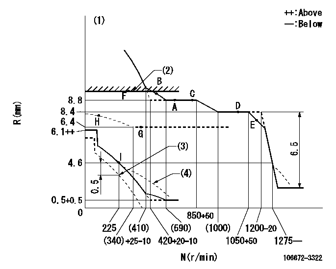
(1)Perform governor adjustment at an ambient temperature of at least 15 deg C (boost compensator start spring is shape memory alloy).
(2)RACK LIMIT: RAL
(3)Set idle at delivery
(4)Damper spring setting: DL
----------
RAL=9.2+0.2mm DL=3.6-0.2mm
----------
----------
RAL=9.2+0.2mm DL=3.6-0.2mm
----------
Speed control lever angle

F:Full speed
----------
----------
a=8deg+-5deg
----------
----------
a=8deg+-5deg
0000000901

F:Full load
I:Idle
(1)Set point I
(2)At delivery
----------
----------
a=25deg+-5deg b=45deg+-3deg c=47deg+-5deg
----------
----------
a=25deg+-5deg b=45deg+-3deg c=47deg+-5deg
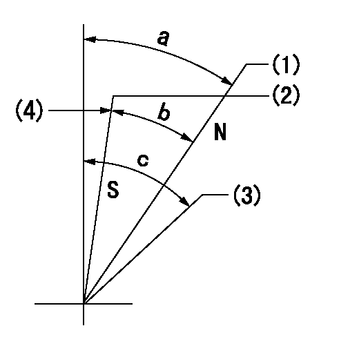
Stop lever angle

N:Engine manufacturer's normal use
S:Stop the pump.
(1)Rack position = aa
(2)Rack position bb
(3)Free (at delivery)
(4)Set the stopper bolt (apply red paint).
----------
aa=12mm bb=2.5-0.5mm
----------
a=40deg+-5deg b=30deg+-5deg c=(50deg)
----------
aa=12mm bb=2.5-0.5mm
----------
a=40deg+-5deg b=30deg+-5deg c=(50deg)
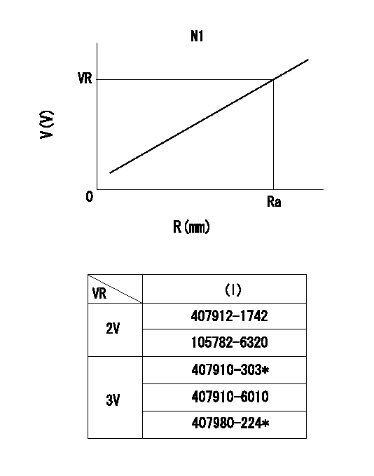
0000001501 RACK SENSOR

R:Rack position (mm)
V:Voltage (V)
After installing the rack sensor, confirm the output value (VR).
----------
N1=650r/min Ra=8.8mm VR=1.7+-0.01V
----------
----------
N1=650r/min Ra=8.8mm VR=1.7+-0.01V
----------
Timing setting

(1)Pump vertical direction
(2)Coupling's key groove position at No 1 cylinder's beginning of injection
(3)-
(4)-
----------
----------
a=(0deg)
----------
----------
a=(0deg)
Information:
03Jul2007
U-305
A-248
D-257
O-277
Parts stock action only
PRODUCT IMPROVEMENT PROGRAM FOR INSPECTING AND REMOVING 8N7005 INJECTORS FROM DEALER PARTS STOCK THAT ARE NOT PACKAGED IN THE PROPER CATERPILLAR PACKAGE AND CATERPILLAR LABEL
1254 7750 1252 PI70234
The information supplied in this service letter may not be valid after the termination date of this program.Do not perform the work outlined in this Service Letter after the termination date without first contacting your Caterpillar product analyst.
TERMINATION DATE
31Oct2007
PROBLEM
Some 8N7005 Fuel Valve Nozzles have been shipped in incorrect Packaging. The package does not have the standard Caterpillar label. The Parts do not have the Caterpillar Logo.
ACTION REQUIRED
Inspect 8N7005 Fuel Valve Nozzles in inventory. Confirm that the injectors are packaged in Caterpillar packaging and Caterpillar label with Caterpillar Logo on the parts.
Image 1 shows the proper packaging and branding on the right side and the improper packaging on the left.
Image 2 shows the proper Caterpillar Logo and the left side shows the nozzles with the incorrect packaging and other identifying marks.
Image1
Image2
SERVICE CLAIM ALLOWANCES
Submit one claim for all parts removed from dealer parts stock.
PARTS DISPOSITION
Return parts to address below to the attn: Clark Hopkins
For NACD
Caterpillar Inc.
Attn: Supplier Recovery
Service Claims Room
8201 N. University
Peoria, IL 61615