Information injection-pump assembly
ZEXEL
106672-3301
1066723301
HINO
220005350C
220005350c
Rating:
Cross reference number
ZEXEL
106672-3301
1066723301
HINO
220005350C
220005350c
Zexel num
Bosch num
Firm num
Name
106672-3301
220005350C HINO
INJECTION-PUMP ASSEMBLY
K13C * K
K13C * K
Calibration Data:
Adjustment conditions
Test oil
1404 Test oil ISO4113 or {SAEJ967d}
1404 Test oil ISO4113 or {SAEJ967d}
Test oil temperature
degC
40
40
45
Nozzle and nozzle holder
105780-8140
Bosch type code
EF8511/9A
Nozzle
105780-0000
Bosch type code
DN12SD12T
Nozzle holder
105780-2080
Bosch type code
EF8511/9
Opening pressure
MPa
17.2
Opening pressure
kgf/cm2
175
Injection pipe
Outer diameter - inner diameter - length (mm) mm 8-3-600
Outer diameter - inner diameter - length (mm) mm 8-3-600
Overflow valve
134424-1720
Overflow valve opening pressure
kPa
162
147
177
Overflow valve opening pressure
kgf/cm2
1.65
1.5
1.8
Tester oil delivery pressure
kPa
157
157
157
Tester oil delivery pressure
kgf/cm2
1.6
1.6
1.6
Direction of rotation (viewed from drive side)
Left L
Left L
Injection timing adjustment
Direction of rotation (viewed from drive side)
Left L
Left L
Injection order
1-4-2-6-
3-5
Pre-stroke
mm
4.4
4.34
4.4
Beginning of injection position
Drive side NO.1
Drive side NO.1
Difference between angles 1
Cal 1-4 deg. 60 59.75 60.25
Cal 1-4 deg. 60 59.75 60.25
Difference between angles 2
Cyl.1-2 deg. 120 119.75 120.25
Cyl.1-2 deg. 120 119.75 120.25
Difference between angles 3
Cal 1-6 deg. 180 179.75 180.25
Cal 1-6 deg. 180 179.75 180.25
Difference between angles 4
Cal 1-3 deg. 240 239.75 240.25
Cal 1-3 deg. 240 239.75 240.25
Difference between angles 5
Cal 1-5 deg. 300 299.75 300.25
Cal 1-5 deg. 300 299.75 300.25
Injection quantity adjustment
Adjusting point
A
Rack position
9.2
Pump speed
r/min
650
650
650
Average injection quantity
mm3/st.
183.2
181.2
185.2
Max. variation between cylinders
%
0
-2
2
Basic
*
Fixing the lever
*
Boost pressure
kPa
32
32
Boost pressure
mmHg
240
240
Injection quantity adjustment_02
Adjusting point
B
Rack position
9.3
Pump speed
r/min
1000
1000
1000
Average injection quantity
mm3/st.
191.5
188.5
194.5
Max. variation between cylinders
%
0
-5
5
Fixing the lever
*
Boost pressure
kPa
32
32
Boost pressure
mmHg
240
240
Injection quantity adjustment_03
Adjusting point
C
Rack position
8.4
Pump speed
r/min
1075
1075
1075
Average injection quantity
mm3/st.
169.5
163.5
175.5
Fixing the lever
*
Boost pressure
kPa
32
32
Boost pressure
mmHg
240
240
Injection quantity adjustment_04
Adjusting point
E
Rack position
4.3+-0.5
Pump speed
r/min
225
225
225
Average injection quantity
mm3/st.
9.4
6.4
12.4
Max. variation between cylinders
%
0
-15
15
Fixing the rack
*
Boost pressure
kPa
0
0
0
Boost pressure
mmHg
0
0
0
Injection quantity adjustment_05
Adjusting point
F
Rack position
7
Pump speed
r/min
400
400
400
Average injection quantity
mm3/st.
128
126
130
Fixing the lever
*
Boost pressure
kPa
0
0
0
Boost pressure
mmHg
0
0
0
Boost compensator adjustment
Pump speed
r/min
650
650
650
Rack position
7
Boost pressure
kPa
3.3
3.3
5.3
Boost pressure
mmHg
25
25
40
Boost compensator adjustment_02
Pump speed
r/min
650
650
650
Rack position
9.2
Boost pressure
kPa
18.7
18.7
18.7
Boost pressure
mmHg
140
140
140
Test data Ex:
Governor adjustment
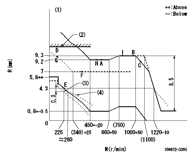
N:Pump speed
R:Rack position (mm)
(1)Perform governor adjustment at an ambient temperature of at least 15 deg C (boost compensator start spring is shape memory alloy).
(2)RACK LIMIT
(3)Set idle at delivery
(4)Damper spring setting: DL
----------
DL=3.8-0.2mm
----------
----------
DL=3.8-0.2mm
----------
Speed control lever angle

F:Full speed
----------
----------
a=17deg+-5deg
----------
----------
a=17deg+-5deg
0000000901
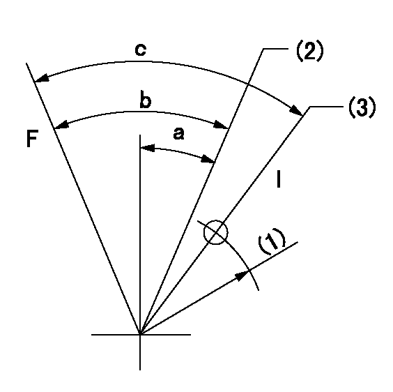
F:Full load
I:Idle
(1)R = aa
(2)Point E setting
(2)At delivery
----------
aa=45mm
----------
a=25deg+-5deg b=46deg+-3deg c=48deg+-5deg
----------
aa=45mm
----------
a=25deg+-5deg b=46deg+-3deg c=48deg+-5deg
Stop lever angle
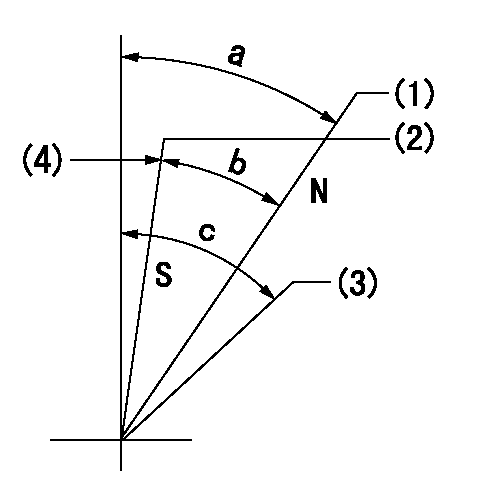
N:Engine manufacturer's normal use
S:Stop the pump.
(1)Rack position = aa
(2)Rack position bb
(3)Free (at delivery)
(4)Set the stopper bolt (apply red paint).
----------
aa=12mm bb=2.5-0.5mm
----------
a=40deg+-5deg b=30deg+-5deg c=(50deg)
----------
aa=12mm bb=2.5-0.5mm
----------
a=40deg+-5deg b=30deg+-5deg c=(50deg)
0000001501 RACK SENSOR
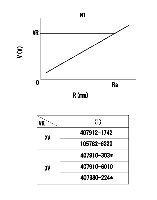
R:Rack position (mm)
V:Voltage (V)
After installing the rack sensor, confirm the output value (VR).
----------
N1=950r/min Ra=9.3mm VR=1.7+-0.01V
----------
----------
N1=950r/min Ra=9.3mm VR=1.7+-0.01V
----------
Timing setting

(1)Pump vertical direction
(2)Coupling's key groove position at No 1 cylinder's beginning of injection
(3)-
(4)-
----------
----------
a=(5deg)
----------
----------
a=(5deg)
Information:
Center Bushing Check new bushings using the table below. Commutator and Drive End Bushing Specifications*I.D. of bushing ... 0.6693 to 0.6704 in.(17.000 to 17.028 mm)Oil clearance** ... 0.0036 to 0.0070 in.(0.091 to 0.178 mm)Maximum clearance** ... 0.016 in.(0.41 mm)Bushing depth ... 0.008 to 0.022 in.(0.20 to 0.56 mm)*Reaming may be necessary after installation. Center Bushing SpecificationsI.D. of bushing ... 1.182 to 1.184 in.(30.02 to 30.07 mm)Maximum clearance** ... 0.0236 in.(0.599 mm)Bushing depth ... 0.017 to 0.032 in.(0.43 to 0.81 mm)**The clearance is the difference between the shaft and the I.D. of the bushing.Armature
Check armature for straightness. Runout should not exceed 0.006 inch (0.15 mm). Maximum commutator runout is 0.016 inch (0.41 mm). If necessary, turn commutator and undercut insulation to 1/32-inch (0.794 mm). Undercut should never be less than 0.008 inch (0.20 mm) Commutator O.D. must be 1.77 inches (45.0 mm) or more. Clean copper dust from between the segments.Check armature for opens, shorts and grounds. Burned edge of commutator indicates an open circuit. Short Circuit TestPlace the armature in a growler and hold a hacksaw blade above each slot while slowly rotating the armature. If a coil is shorted, the blade will be attracted to and repelled from the slot.A short circuit most often occurs because of copper dust or filings between two commutator segments. A short of this nature can be corrected by removal of such material.
Fig. 22-Armature Ground TestWith the ohmmeter set to read on its highest scale, place one test lead on the commutator and the other lead on the armature core or shaft (Fig. 22). If the test meter indicator swings towards zero, the armature is grounded. Replace armature.
Fig. 23-Open Circuit TestWith the ohmmeter set to read on its lowest scale, place one test lead on the commutator segment and the other test lead on an adjacent segment (Fig. 23). Repeat this operation for all segments by moving one lead at a time. If the test meter indicator does not swing to zero and remains stationary, the armature coil between these two segements is open. Replace armature.Burned commutator segments are usually an indication of an open circuited coil.Overrunning Clutch and Pinion
Do not immerse the overrunning clutch and pinion 4, Fig. 21 in a cleaning solvent. The unit has been prelubricated and solvent will wash lubricant away. It may be cleaned with a cloth moistened with a cleaning solvent and wiped dry.Rotate the pinion. Pinion gear should rotate smoothly (but not necessarily easily) in one direction, and should not rotate in the opposite direction.If the pinion gear does not rotate smoothly, or if it is worn, chipped, or burred, it should be replaced.Field Windings and Shunt Windings
Grounded Circuit Test (Fig. 24)
Fig. 24-Grounded Circuit TestRemove the screw and hang the eyelet terminal in the air. Using an ohmmeter set to read on its highest scale, place one test lead on the copper terminal bolt and the other lead on a clean spot of the field frame (Fig. 24). If the ohmmeter
Have questions with 106672-3301?
Group cross 106672-3301 ZEXEL
Hino
106672-3301
220005350C
INJECTION-PUMP ASSEMBLY
K13C
K13C