Information injection-pump assembly
BOSCH
9 400 617 076
9400617076
ZEXEL
106672-3253
1066723253
HINO
220004985A
220004985a

Rating:
Service parts 106672-3253 INJECTION-PUMP ASSEMBLY:
1.
_
5.
AUTOM. ADVANCE MECHANIS
7.
COUPLING PLATE
8.
_
9.
_
11.
Nozzle and Holder
236001740A
12.
Open Pre:MPa(Kqf/cm2)
16.7(170)/27.5(280)
15.
NOZZLE SET
Include in #1:
106672-3253
as INJECTION-PUMP ASSEMBLY
Cross reference number
BOSCH
9 400 617 076
9400617076
ZEXEL
106672-3253
1066723253
HINO
220004985A
220004985a
Zexel num
Bosch num
Firm num
Name
106672-3253
9 400 617 076
220004985A HINO
INJECTION-PUMP ASSEMBLY
EP2 K
EP2 K
106672-3253
9 400 617 076
S220004985A HINO
INJECTION-PUMP ASSEMBLY
EP2 A K
EP2 A K
Calibration Data:
Adjustment conditions
Test oil
1404 Test oil ISO4113 or {SAEJ967d}
1404 Test oil ISO4113 or {SAEJ967d}
Test oil temperature
degC
40
40
45
Nozzle and nozzle holder
105780-8140
Bosch type code
EF8511/9A
Nozzle
105780-0000
Bosch type code
DN12SD12T
Nozzle holder
105780-2080
Bosch type code
EF8511/9
Opening pressure
MPa
17.2
Opening pressure
kgf/cm2
175
Injection pipe
Outer diameter - inner diameter - length (mm) mm 8-3-600
Outer diameter - inner diameter - length (mm) mm 8-3-600
Overflow valve (drive side)
134424-1420
Overflow valve opening pressure (drive side)
kPa
162
147
177
Overflow valve opening pressure (drive side)
kgf/cm2
1.65
1.5
1.8
Overflow valve (governor side)
134424-1720
Overflow valve opening pressure (governor side)
kPa
162
147
177
Overflow valve opening pressure (governor side)
kgf/cm2
1.65
1.5
1.8
Tester oil delivery pressure
kPa
157
157
157
Tester oil delivery pressure
kgf/cm2
1.6
1.6
1.6
Direction of rotation (viewed from drive side)
Right R
Right R
Injection timing adjustment
Direction of rotation (viewed from drive side)
Right R
Right R
Injection order
1-4-2-6-
3-5
Pre-stroke
mm
4.5
4.44
4.5
Beginning of injection position
Drive side NO.1
Drive side NO.1
Difference between angles 1
Cal 1-4 deg. 60 59.75 60.25
Cal 1-4 deg. 60 59.75 60.25
Difference between angles 2
Cyl.1-2 deg. 120 119.75 120.25
Cyl.1-2 deg. 120 119.75 120.25
Difference between angles 3
Cal 1-6 deg. 180 179.75 180.25
Cal 1-6 deg. 180 179.75 180.25
Difference between angles 4
Cal 1-3 deg. 240 239.75 240.25
Cal 1-3 deg. 240 239.75 240.25
Difference between angles 5
Cal 1-5 deg. 300 299.75 300.25
Cal 1-5 deg. 300 299.75 300.25
Injection quantity adjustment
Adjusting point
A
Rack position
8.8
Pump speed
r/min
650
650
650
Average injection quantity
mm3/st.
173
171
175
Max. variation between cylinders
%
0
-2
2
Basic
*
Fixing the lever
*
Boost pressure
kPa
53.3
53.3
Boost pressure
mmHg
400
400
Injection quantity adjustment_02
Adjusting point
B
Rack position
9.1
Pump speed
r/min
500
500
500
Average injection quantity
mm3/st.
183.5
180.5
186.5
Max. variation between cylinders
%
0
-5
5
Fixing the lever
*
Boost pressure
kPa
53.3
53.3
Boost pressure
mmHg
400
400
Injection quantity adjustment_03
Adjusting point
C
Rack position
8.8
Pump speed
r/min
850
850
850
Average injection quantity
mm3/st.
171
165
177
Fixing the lever
*
Boost pressure
kPa
53.3
53.3
Boost pressure
mmHg
400
400
Injection quantity adjustment_04
Adjusting point
D
Rack position
8.4
Pump speed
r/min
1050
1050
1050
Average injection quantity
mm3/st.
160.5
157.5
163.5
Max. variation between cylinders
%
0
-5
5
Fixing the lever
*
Boost pressure
kPa
53.3
53.3
Boost pressure
mmHg
400
400
Injection quantity adjustment_05
Adjusting point
E
Rack position
7.4
Pump speed
r/min
1150
1150
1150
Average injection quantity
mm3/st.
137
132
142
Fixing the lever
*
Boost pressure
kPa
53.3
53.3
Boost pressure
mmHg
400
400
Injection quantity adjustment_06
Adjusting point
F
Rack position
9.2+0.2
Pump speed
r/min
300
300
300
Average injection quantity
mm3/st.
186
180
192
Fixing the lever
*
Boost pressure
kPa
53.3
53.3
Boost pressure
mmHg
400
400
Rack limit
*
Injection quantity adjustment_07
Adjusting point
G
Rack position
6.4
Pump speed
r/min
400
400
400
Average injection quantity
mm3/st.
86
84
88
Fixing the lever
*
Boost pressure
kPa
0
0
0
Boost pressure
mmHg
0
0
0
Injection quantity adjustment_08
Adjusting point
I
Rack position
4.6+-0.5
Pump speed
r/min
225
225
225
Average injection quantity
mm3/st.
11
8
14
Max. variation between cylinders
%
0
-15
15
Fixing the rack
*
Boost pressure
kPa
0
0
0
Boost pressure
mmHg
0
0
0
Boost compensator adjustment
Pump speed
r/min
650
650
650
Rack position
6.4
Boost pressure
kPa
9.3
7.3
9.3
Boost pressure
mmHg
70
55
70
Boost compensator adjustment_02
Pump speed
r/min
650
650
650
Rack position
8.8
Boost pressure
kPa
40
40
40
Boost pressure
mmHg
300
300
300
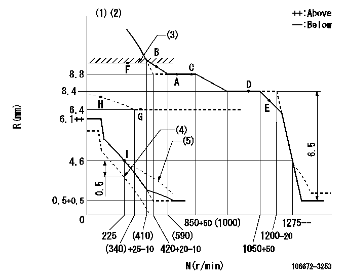
Test data Ex:
Governor adjustment

N:Pump speed
R:Rack position (mm)
(1)Lever ratio: RT
(2)Target shim dimension: TH
(3)RACK LIMIT: RAL
(4)Set idle at delivery
(5)Damper spring setting: DL
----------
RT=0.8 TH=1.5mm RAL=9.2+0.2mm DL=4.4-0.2mm
----------
----------
RT=0.8 TH=1.5mm RAL=9.2+0.2mm DL=4.4-0.2mm
----------
Speed control lever angle

F:Full speed
----------
----------
a=8deg+-5deg
----------
----------
a=8deg+-5deg
0000000901

F:Full load
I:Idle
(1)Set point I
(2)At delivery
----------
----------
a=25deg+-5deg b=45deg+-3deg c=47deg+-5deg
----------
----------
a=25deg+-5deg b=45deg+-3deg c=47deg+-5deg
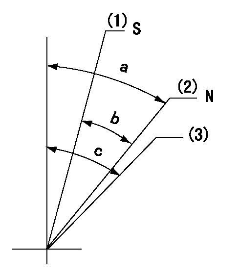
Stop lever angle

N:Engine manufacturer's normal use
S:Stop the pump.
(1)Set the stopper bolt at rack = aa (apply red paint).
(2)Rack position bb
(3)Free (at delivery)
----------
aa=2.5-0.5mm bb=12mm
----------
a=40deg+-5deg b=30deg+-5deg c=(50deg)
----------
aa=2.5-0.5mm bb=12mm
----------
a=40deg+-5deg b=30deg+-5deg c=(50deg)
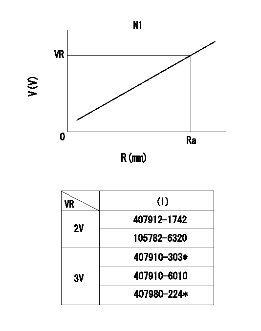
0000001501 RACK SENSOR

R:Rack position (mm)
V:Voltage (V)
After installing the rack sensor, confirm the output value (VR).
----------
N1=650r/min Ra=8.8mm VR=1.7+-0.01V
----------
----------
N1=650r/min Ra=8.8mm VR=1.7+-0.01V
----------
Timing setting

(1)Pump vertical direction
(2)Coupling's key groove position at No 1 cylinder's beginning of injection
(3)-
(4)-
----------
----------
a=(0deg)
----------
----------
a=(0deg)
Information:
Repair
Pistons
See Group 0404 for piston-to-cylinder liner measurements.Remove piston rings. IMPORTANT: Do not soak pistons more than 60 minutes.
Avoid contact of solution with skin or eyes.
Soak pistons in 50 percent solution of "Mr. Clean" (or equivalent) and water for 30 to 60 minutes. IMPORTANT: Never clean pistons with wire brush or abrasives.Scrub piston with stiff bristle brush.Rinse pistons in clean water and dry with clean towels. Two different types of pistons marked "B" and "H" on their top face can be selectively installed on 3179D, 4239 D & T, and 6359 D & T engines for a better dead space control inside the cylinder. The difference between the two pistons is 0.006 inch (0.15 mm) on the distance between the piston pin center and the piston top.When replacing pistons, install pistons of the same type as the original.When replacing cylinder block or when mark on piston is no longer visible, determine piston type as follows using gauge KCD-10003.Install cylinder liners and crankshaft with bearings in cylinder block.Secure cylinder liners, using cap screws and washers.Install a "B" type piston with its connecting rod and secure with cap.
Fig. 3A-Determining Type of Piston Using Gauge KCD-10003Place gauge KCD-10003 on liner flange and press downward (3A).Turn crankshaft until piston is in "TDC" position.When piston lightly touches gauge then use "B" type pistons.When pisotn does not contact gauge, then use "H" type pistons.If no gauge is available, proceed as follows:Install a "B" type piston with its connecting rod and secure with cap.Using a dial indicator measure protrusion of each piston (at TDC) above face of cylinder block. Measure at cylinder block centerlineInstall a "B" type piston if protrusion is above or equal to 0.004 in. (0.1 mm) and an "H" type piston if protrusion is below 0.004 in. (0.1 mm). IMPORTANT: Maximum allowable piston standout is 0.012 in. (0.30 mm).Piston Rings and Ring Grooves
Do not re-use piston rings.
Fig. 4-JDE-62 Ring Groove Wear GaugeUsing JDE-62 Ring Groove Wear Gauge (Fig. 4), measure top ring groove. If gauge shoulders contact the ring land, groove is excessively worn.Measure rectangular ring grooves with proper new ring and a feeler gauge.
Fig. 5-Measure Ring GroovesRing groove clearance (maximum) (Fig. 5) ... 0.008 inch(0.20 mm)Piston Pin Bore
Fig. 6-Piston Pin AssemblyPiston pins must fit piston pin bore with a thumb press fit (Fig. 6).Replace piston if piston pin bore is worn.Piston Pin Bushing
Fig. 7-Piston PinMeasure piston pin bushing inside diameter (Fig. 8) with bushing in connecting rod.Piston pin bushing size; If piston pin size is not within specifications, install a new one.Piston Pin Bushing
Fig. 8-Piston Pin BushingMeasure piston pin bushing inside diameter (Fig. 8) with bushing in connecting rod.Piston pin bushing size; Check piston pin size (Group 0403, above).Find the difference, piston pin/bushing clearance, between the piston pin size and the bushing size. The clearance (Fig. 9) must be 0.0008 to 0.0022 in. (0.02 to 0.06 mm).
Fig. 9-Piston Pin/Bushing ClearanceIf bushing size is not within specifications, install a new one.
Fig. 10-Bushing Remover and InstallerUsing the bushing remover and installer listed below,
Have questions with 106672-3253?
Group cross 106672-3253 ZEXEL
Hino
106672-3253
9 400 617 076
220004985A
INJECTION-PUMP ASSEMBLY
EP2
EP2
106672-3253
9 400 617 076
S220004985A
INJECTION-PUMP ASSEMBLY
EP2
EP2