Information injection-pump assembly
BOSCH
9 400 612 310
9400612310
ZEXEL
106671-9961
1066719961

Rating:
Service parts 106671-9961 INJECTION-PUMP ASSEMBLY:
1.
_
7.
COUPLING PLATE
8.
_
9.
_
10.
NOZZLE AND HOLDER ASSY
11.
Nozzle and Holder
12.
Open Pre:MPa(Kqf/cm2)
13.
NOZZLE-HOLDER
14.
NOZZLE
15.
NOZZLE SET
Include in #1:
106671-9961
as INJECTION-PUMP ASSEMBLY
Cross reference number
BOSCH
9 400 612 310
9400612310
ZEXEL
106671-9961
1066719961
Zexel num
Bosch num
Firm num
Name
106671-9961
9 400 612 310
DAEWOO
INJECTION-PUMP ASSEMBLY
D1146TI K 14CA INJECTION PUMP ASSY PE6P,6PD PE
D1146TI K 14CA INJECTION PUMP ASSY PE6P,6PD PE
Calibration Data:
Adjustment conditions
Test oil
1404 Test oil ISO4113 or {SAEJ967d}
1404 Test oil ISO4113 or {SAEJ967d}
Test oil temperature
degC
40
40
45
Nozzle and nozzle holder
105780-8250
Bosch type code
1 688 901 101
Nozzle
105780-0120
Bosch type code
1 688 901 990
Nozzle holder
105780-2190
Opening pressure
MPa
20.7
Opening pressure
kgf/cm2
211
Injection pipe
Outer diameter - inner diameter - length (mm) mm 8-3-600
Outer diameter - inner diameter - length (mm) mm 8-3-600
Overflow valve
134424-4120
Overflow valve opening pressure
kPa
255
255
255
Overflow valve opening pressure
kgf/cm2
2.6
2.6
2.6
Tester oil delivery pressure
kPa
255
255
255
Tester oil delivery pressure
kgf/cm2
2.6
2.6
2.6
Direction of rotation (viewed from drive side)
Right R
Right R
Injection timing adjustment
Direction of rotation (viewed from drive side)
Right R
Right R
Injection order
1-5-3-6-
2-4
Pre-stroke
mm
3.9
3.85
3.95
Beginning of injection position
Drive side NO.1
Drive side NO.1
Difference between angles 1
Cal 1-5 deg. 60 59.5 60.5
Cal 1-5 deg. 60 59.5 60.5
Difference between angles 2
Cal 1-3 deg. 120 119.5 120.5
Cal 1-3 deg. 120 119.5 120.5
Difference between angles 3
Cal 1-6 deg. 180 179.5 180.5
Cal 1-6 deg. 180 179.5 180.5
Difference between angles 4
Cyl.1-2 deg. 240 239.5 240.5
Cyl.1-2 deg. 240 239.5 240.5
Difference between angles 5
Cal 1-4 deg. 300 299.5 300.5
Cal 1-4 deg. 300 299.5 300.5
Injection quantity adjustment
Adjusting point
-
Rack position
13.4
Pump speed
r/min
1100
1100
1100
Average injection quantity
mm3/st.
136
134
138
Max. variation between cylinders
%
0
-2
2
Basic
*
Fixing the rack
*
Standard for adjustment of the maximum variation between cylinders
*
Injection quantity adjustment_02
Adjusting point
Z
Rack position
8+-0.5
Pump speed
r/min
440
440
440
Average injection quantity
mm3/st.
16
14.5
17.5
Max. variation between cylinders
%
0
-15
15
Fixing the rack
*
Standard for adjustment of the maximum variation between cylinders
*
Injection quantity adjustment_03
Adjusting point
A
Rack position
R1(13.4)
Pump speed
r/min
1100
1100
1100
Average injection quantity
mm3/st.
136
134
138
Basic
*
Fixing the lever
*
Boost pressure
kPa
46.7
46.7
Boost pressure
mmHg
350
350
Injection quantity adjustment_04
Adjusting point
B
Rack position
R1-1.5
Pump speed
r/min
600
600
600
Average injection quantity
mm3/st.
132
122
142
Fixing the lever
*
Boost pressure
kPa
46.7
46.7
Boost pressure
mmHg
350
350
Boost compensator adjustment
Pump speed
r/min
500
500
500
Rack position
R2-1.6
Boost pressure
kPa
18.7
17.4
20
Boost pressure
mmHg
140
130
150
Boost compensator adjustment_02
Pump speed
r/min
500
500
500
Rack position
R2[R1-1.
5]
Boost pressure
kPa
33.3
33.3
33.3
Boost pressure
mmHg
250
250
250
Timer adjustment
Pump speed
r/min
750--
Advance angle
deg.
0
0
0
Remarks
Start
Start
Timer adjustment_02
Pump speed
r/min
700
Advance angle
deg.
0.5
Timer adjustment_03
Pump speed
r/min
930
Advance angle
deg.
4
3.5
4.5
Remarks
Finish
Finish
Test data Ex:
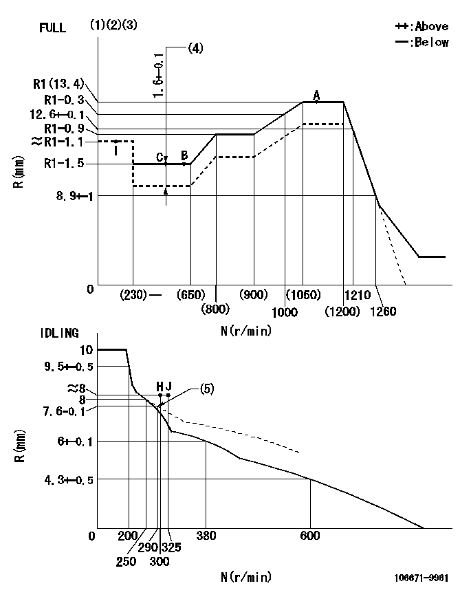
Governor adjustment

N:Pump speed
R:Rack position (mm)
(1)Torque cam stamping: T1
(2)Tolerance for racks not indicated: +-0.05mm.
(3)Microswitch adjustment unnecessary.
(4)Boost compensator stroke
(5)Damper spring setting
----------
T1=AG99
----------
----------
T1=AG99
----------
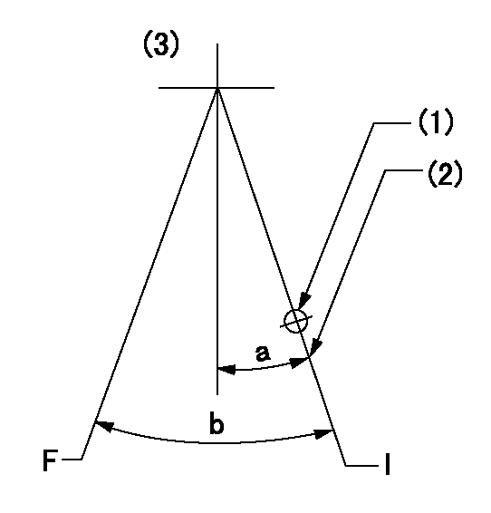
Speed control lever angle

F:Full speed
I:Idle
(1)Use the hole at R = aa
(2)Stopper bolt setting
(3)Viewed from feed pump side.
----------
aa=70mm
----------
a=14deg+-5deg b=40.5deg+-3deg
----------
aa=70mm
----------
a=14deg+-5deg b=40.5deg+-3deg
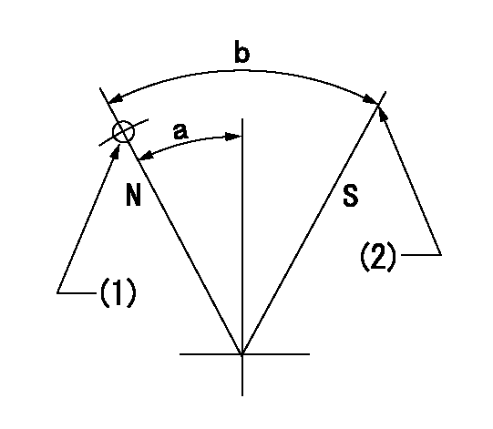
Stop lever angle

N:Pump normal
S:Stop the pump.
(1)Use the hole at R = aa
(2)At pump speed bb and rack position cc, set the stopper bolt.
----------
aa=40mm bb=0r/min cc=1.5+-0.3mm
----------
a=20deg+-5deg b=44deg+-5deg
----------
aa=40mm bb=0r/min cc=1.5+-0.3mm
----------
a=20deg+-5deg b=44deg+-5deg
Timing setting

(1)Pump vertical direction
(2)Coupling's key groove position for the No. 6 cylinder's beginning of injection
(3)-
(4)-
----------
----------
a=(50deg)
----------
----------
a=(50deg)
Information:
Introduction
This Special Instruction provides information to reset Diesel Particulate Filter (DPF) soot load on certain XQ60 rental generator sets.Do not perform any procedure in this Special Instruction until you have read the information and you understand the information.Safety Section
Do not perform any procedure in this Special Instruction until you have read this Special Instruction and you understand this information. Use only proper tools and observe all precautions that pertain to the use of those tools. Failure to follow these procedures can result in personal injury. The following procedures should be observed.Work safely. Most accidents that involve product operation, maintenance, and repair are caused by failure to observe basic safety rules or precautions. An accident can often be avoided by recognizing potentially hazardous situations before an accident occurs.A person must be alert to potential hazards. This person must also have the necessary training, skills, and tools to perform these functions properly.Safety precautions and warnings are provided in this instruction and on the product. If these hazard warnings are not heeded, bodily injury or death could occur to you or to other persons. Caterpillar cannot anticipate every possible circumstance of a potential hazard.Therefore, the warnings in this publication and the warnings that are on the product are not all inclusive. Avoid using a tool, a procedure, a work method, or operating technique that is not recommended by Caterpillar.Ensure that the product will not be damaged or the product will be made unsafe by the operation, lubrication, maintenance, or the repair procedures.
Do not operate or work on this product unless you have read and understood the instruction and warnings in the relevant Operation and Maintenance Manuals and relevant service literature. Failure to follow the instructions or heed the warnings could result in injury or death. Proper care is your responsibility.
Failure to follow all safety guidelines prescribed in this document and by governing authorities and regulatory agencies may result in severe injury or death of personnel or machine damage.
Reset Procedure for DPF Soot Load
Perform the following procedure to reset DPF soot load:
Turn the generator set battery disconnect to ON position.
Verify power to Electronic Modular Control Panel (EMCP).
Connect Cat® Electronic Technician (Cat ET) service tool.
Connect to Cat ET - Configuration EMCP Controller.
Update "RO#2" on EMCP from "Eng Start Initiated" to "Auto Mode".
Change the generator set to auto mode. Changing the generator set to auto mode applies power to engine Electronic Control Module (ECM).
Verify whether the active code in Cat ET is "3719-0 - High DPF Soot Load".
Illustration 1 g06574660
Electronic Modular Control Panel
Illustration 2 g06574661
Engine Electronic Control Module
Check whether the parameters shown in Illustration 1 and Illustration 2 are set in "EMCP" and "Engine ECM" configurations.
Illustration 3 g06574662
Perform DPF soot load reset by navigating "Component Replacement Resets".
Verify DPF Soot Load value in "Engine Status" screen.
Verify the active codes.
Stop the unit in EMCP.
Update "RO#2" from "Auto Mode" to "Eng Start Initiated".
Check whether the unit is set to run at idle speed in "EMCP".
Run the unit and check whether "low idle speed" is 1200 rpm. Refer to Illustration 3.
Manually
Have questions with 106671-9961?
Group cross 106671-9961 ZEXEL
Dpico
Daewoo
106671-9961
9 400 612 310
INJECTION-PUMP ASSEMBLY
D1146TI
D1146TI