Information injection-pump assembly
BOSCH
F 019 Z20 101
f019z20101
ZEXEL
106671-9890
1066719890
Rating:
Cross reference number
BOSCH
F 019 Z20 101
f019z20101
ZEXEL
106671-9890
1066719890
Zexel num
Bosch num
Firm num
Name
106671-9890
F 019 Z20 101
DPICO
INJECTION-PUMP ASSEMBLY
Q-DD Q
Q-DD Q
Calibration Data:
Adjustment conditions
Test oil
1404 Test oil ISO4113 or {SAEJ967d}
1404 Test oil ISO4113 or {SAEJ967d}
Test oil temperature
degC
40
40
45
Nozzle and nozzle holder
105780-8140
Bosch type code
EF8511/9A
Nozzle
105780-0000
Bosch type code
DN12SD12T
Nozzle holder
105780-2080
Bosch type code
EF8511/9
Opening pressure
MPa
17.2
Opening pressure
kgf/cm2
175
Injection pipe
Outer diameter - inner diameter - length (mm) mm 8-3-600
Outer diameter - inner diameter - length (mm) mm 8-3-600
Overflow valve
131424-4420
Overflow valve opening pressure
kPa
157
123
191
Overflow valve opening pressure
kgf/cm2
1.6
1.25
1.95
Tester oil delivery pressure
kPa
157
157
157
Tester oil delivery pressure
kgf/cm2
1.6
1.6
1.6
Direction of rotation (viewed from drive side)
Right R
Right R
Injection timing adjustment
Direction of rotation (viewed from drive side)
Right R
Right R
Injection order
1-5-3-6-
2-4
Pre-stroke
mm
4.4
4.35
4.45
Beginning of injection position
Governor side NO.1
Governor side NO.1
Difference between angles 1
Cal 1-5 deg. 60 59.5 60.5
Cal 1-5 deg. 60 59.5 60.5
Difference between angles 2
Cal 1-3 deg. 120 119.5 120.5
Cal 1-3 deg. 120 119.5 120.5
Difference between angles 3
Cal 1-6 deg. 180 179.5 180.5
Cal 1-6 deg. 180 179.5 180.5
Difference between angles 4
Cyl.1-2 deg. 240 239.5 240.5
Cyl.1-2 deg. 240 239.5 240.5
Difference between angles 5
Cal 1-4 deg. 300 299.5 300.5
Cal 1-4 deg. 300 299.5 300.5
Injection quantity adjustment
Adjusting point
-
Rack position
11.5
Pump speed
r/min
700
700
700
Each cylinder's injection qty
mm3/st.
141
137.5
144.5
Basic
*
Fixing the rack
*
Standard for adjustment of the maximum variation between cylinders
*
Injection quantity adjustment_02
Adjusting point
C
Rack position
R3(5.5)
Pump speed
r/min
325
325
325
Each cylinder's injection qty
mm3/st.
11
9.4
12.6
Fixing the rack
*
Standard for adjustment of the maximum variation between cylinders
*
Injection quantity adjustment_03
Adjusting point
A
Rack position
R1(11.5)
Pump speed
r/min
700
700
700
Average injection quantity
mm3/st.
141
140
142
Basic
*
Fixing the lever
*
Boost pressure
kPa
77.3
77.3
Boost pressure
mmHg
580
580
Injection quantity adjustment_04
Adjusting point
G
Rack position
-
Pump speed
r/min
100
100
100
Average injection quantity
mm3/st.
110
70
150
Fixing the lever
*
Boost pressure
kPa
0
0
0
Boost pressure
mmHg
0
0
0
Boost compensator adjustment
Pump speed
r/min
550
550
550
Rack position
R2-2
Boost pressure
kPa
9.3
8
10.6
Boost pressure
mmHg
70
60
80
Boost compensator adjustment_02
Pump speed
r/min
550
550
550
Rack position
R2(R1(11
.5))
Boost pressure
kPa
64
60.7
67.3
Boost pressure
mmHg
480
455
505
Timer adjustment
Pump speed
r/min
650--
Advance angle
deg.
0
0
0
Remarks
Beginning of advance.
Beginning of advance.
Timer adjustment_02
Pump speed
r/min
-
Remarks
Speed, angle are actual measurements.
Speed, angle are actual measurements.
Timer adjustment_03
Pump speed
r/min
(500--)
Advance angle
deg.
0
0
0
Timer adjustment_04
Pump speed
r/min
600
Advance angle
deg.
0.5
Timer adjustment_05
Pump speed
r/min
900
Advance angle
deg.
3.5
2.8
4
Remarks
Finish
Finish
Test data Ex:
Governor adjustment
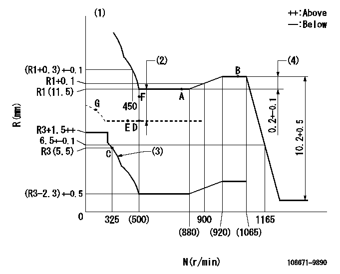
N:Pump speed
R:Rack position (mm)
(1)Tolerance for racks not indicated: +-0.05mm.
(2)Boost compensator stroke: BCL
(3)Damper spring setting: DL
(4)Rack difference between N = N1 and N = N2
----------
BCL=2+-0.1mm DL=(R3-0.2)-0.2mm N1=1000r/min N2=700r/min
----------
----------
BCL=2+-0.1mm DL=(R3-0.2)-0.2mm N1=1000r/min N2=700r/min
----------
Speed control lever angle

F:Full speed
----------
----------
a=(13.5deg)+-5deg
----------
----------
a=(13.5deg)+-5deg
0000000901
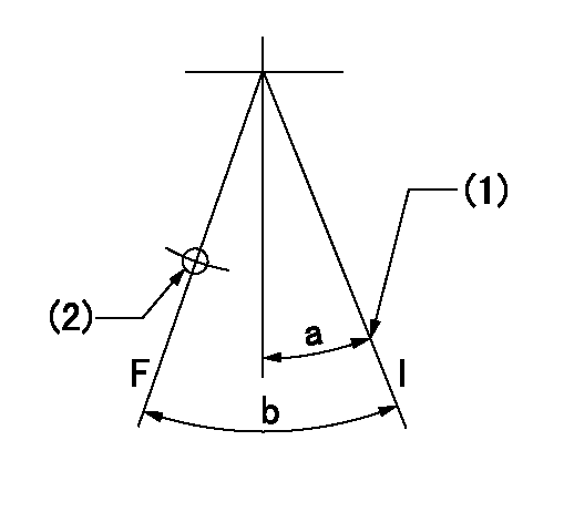
F:Full load
I:Idle
(1)Stopper bolt setting
(2)Use the hole at R = aa
----------
aa=46mm
----------
a=18deg+-5deg b=(31deg)+-3deg
----------
aa=46mm
----------
a=18deg+-5deg b=(31deg)+-3deg
Stop lever angle
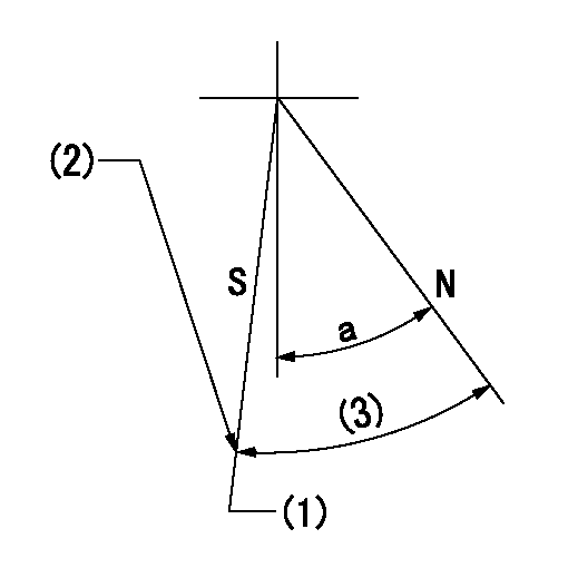
N:Pump normal
S:Stop the pump.
(1)Rack position = actual measurement
(2)Stopper bolt setting
(3)(Actual measurement)
----------
----------
a=38deg+-5deg
----------
----------
a=38deg+-5deg
Timing setting

(1)Pump vertical direction
(2)Coupling's key groove position at No 1 cylinder's beginning of injection
(3)-
(4)-
----------
----------
a=(6deg)
----------
----------
a=(6deg)
Information:
Removal Procedure
Illustration 4 g06465824When Diesel Exhaust Fluid (DEF) lines from the DEF injectors are removed for service, there is a possibility of small DEF quantity to be spilled over the DEF injector body.DEF forms a white, crystalline residue when allowed to dry. This reside can prevent proper sealing of the fittings when the hose is reinstalled. Refer to Illustration 4.DEF Hose Removal Procedure
After the engine is shut off, ensure that the purge cycle is completed before performing the procedure.
Illustration 5 g06465825
Push the hose fitting toward the tube to relieve the force on the hose fitting. Refer to Illustration 5.
Illustration 6 g06465826
Press and hold down the retainer clip button and pull the hose fitting off tube. Refer to Illustration 6.
Illustration 7 g06465828
If hose fitting fails to release, place a compressed air nozzle up against gaps "A" and "B" and blow out dirt and debris for a few seconds on each gap Refer to Illustration 7. Then repeat steps 2 and 3.DEF Hose Cleaning Procedure
Illustration 8 g06465829
DEF and other debris will interfere with the fitting functionality and will prevent sealing of the connector interface. Refer to Illustration 8.
Illustration 9 g06465830
Soak the hose end in distilled water for about a minute. Refer to Illustration 9.
Illustration 10 g06465831
Gently shake the hose dry. Refer to Illustration 10.
Do not use wipes or cloth to wipe the connector. This could introduce fibers into the DEF system and cause DEF pump or DEF injector error codes.DEF Hose Inspection Procedure
Illustration 11 g06465835
Push the end of the retainer clip (D1). Refer to Illustration 11.
Illustration 12 g06465838
Release the force on the clip (D2) to ensure that the clip travels freely. Refer to Illustration 12.
If clip does not travel freely, repeat the DEF hose cleaning procedure.
If clip does not travel freely after two or more cleaning attempts, the clip is damaged and the hose has to be replaced.Installation Procedure of DEF Hose Assembly
Illustration 13 g06465839
Rinse the DEF injector body with distilled water with the electrical connector connected to the injector. Refer to Illustration 13.
Illustration 14 g06465841
Insert the hose into the injector fitting until the retainer clip snaps into place and the tube comes to a stop. Refer to Illustration 14.
Illustration 15 g06465842
Hold the molded portion of the hose and pull away from the injector to ensure it is fully seated and locked in place. Refer to Illustration 15.
If hose does not lock in place and pulls out, the hose end connection or clip has been damaged. Replace the DEF line.
Have questions with 106671-9890?
Group cross 106671-9890 ZEXEL
Dpico
Yanmar
Dpico
Komatsu
Dpico
106671-9890
F 019 Z20 101
INJECTION-PUMP ASSEMBLY
Q-DD
Q-DD