Information injection-pump assembly
BOSCH
F 019 Z20 099
f019z20099
ZEXEL
106671-9851
1066719851
Rating:
Cross reference number
BOSCH
F 019 Z20 099
f019z20099
ZEXEL
106671-9851
1066719851
Zexel num
Bosch num
Firm num
Name
106671-9851
F 019 Z20 099
DPICO
INJECTION-PUMP ASSEMBLY
Q Q
Q Q
Calibration Data:
Adjustment conditions
Test oil
1404 Test oil ISO4113 or {SAEJ967d}
1404 Test oil ISO4113 or {SAEJ967d}
Test oil temperature
degC
40
40
45
Nozzle and nozzle holder
105780-8140
Bosch type code
EF8511/9A
Nozzle
105780-0000
Bosch type code
DN12SD12T
Nozzle holder
105780-2080
Bosch type code
EF8511/9
Opening pressure
MPa
17.2
Opening pressure
kgf/cm2
175
Injection pipe
Outer diameter - inner diameter - length (mm) mm 8-3-600
Outer diameter - inner diameter - length (mm) mm 8-3-600
Overflow valve
131424-4420
Overflow valve opening pressure
kPa
157
123
191
Overflow valve opening pressure
kgf/cm2
1.6
1.25
1.95
Tester oil delivery pressure
kPa
157
157
157
Tester oil delivery pressure
kgf/cm2
1.6
1.6
1.6
Direction of rotation (viewed from drive side)
Right R
Right R
Injection timing adjustment
Direction of rotation (viewed from drive side)
Right R
Right R
Injection order
1-5-3-6-
2-4
Pre-stroke
mm
4.4
4.35
4.45
Beginning of injection position
Governor side NO.1
Governor side NO.1
Difference between angles 1
Cal 1-5 deg. 60 59.5 60.5
Cal 1-5 deg. 60 59.5 60.5
Difference between angles 2
Cal 1-3 deg. 120 119.5 120.5
Cal 1-3 deg. 120 119.5 120.5
Difference between angles 3
Cal 1-6 deg. 180 179.5 180.5
Cal 1-6 deg. 180 179.5 180.5
Difference between angles 4
Cyl.1-2 deg. 240 239.5 240.5
Cyl.1-2 deg. 240 239.5 240.5
Difference between angles 5
Cal 1-4 deg. 300 299.5 300.5
Cal 1-4 deg. 300 299.5 300.5
Injection quantity adjustment
Adjusting point
-
Rack position
13.1
Pump speed
r/min
700
700
700
Each cylinder's injection qty
mm3/st.
169
164.8
173.2
Basic
*
Fixing the rack
*
Standard for adjustment of the maximum variation between cylinders
*
Injection quantity adjustment_02
Adjusting point
C
Rack position
R2(5.6)
Pump speed
r/min
325
325
325
Each cylinder's injection qty
mm3/st.
13.6
11.8
15.4
Fixing the rack
*
Standard for adjustment of the maximum variation between cylinders
*
Injection quantity adjustment_03
Adjusting point
A
Rack position
R1(13.1)
Pump speed
r/min
700
700
700
Average injection quantity
mm3/st.
169
168
170
Basic
*
Fixing the lever
*
Boost pressure
kPa
107
107
Boost pressure
mmHg
800
800
Injection quantity adjustment_04
Adjusting point
B
Rack position
R1(13.1)
Pump speed
r/min
1100
1100
1100
Average injection quantity
mm3/st.
154
150
158
Fixing the lever
*
Boost pressure
kPa
107
107
Boost pressure
mmHg
800
800
Injection quantity adjustment_05
Adjusting point
G
Rack position
-
Pump speed
r/min
100
100
100
Average injection quantity
mm3/st.
120
80
160
Fixing the lever
*
Boost pressure
kPa
0
0
0
Boost pressure
mmHg
0
0
0
Boost compensator adjustment
Pump speed
r/min
600
600
600
Rack position
R3-3.4
Boost pressure
kPa
4
2.7
5.3
Boost pressure
mmHg
30
20
40
Boost compensator adjustment_02
Pump speed
r/min
600
600
600
Rack position
R3(R1(13
.1))
Boost pressure
kPa
93.3
90
96.6
Boost pressure
mmHg
700
675
725
Timer adjustment
Pump speed
r/min
-
Advance angle
deg.
1.5
1
2
Load
0/4
Remarks
Measure speed (beginning of operation).
Measure speed (beginning of operation).
Timer adjustment_02
Pump speed
r/min
-
Advance angle
deg.
0
0
0
Load
0/4
Remarks
Measure the actual speed.
Measure the actual speed.
Timer adjustment_03
Pump speed
r/min
-
Advance angle
deg.
0
0
0
Load
4/4
Remarks
Measure the actual speed.
Measure the actual speed.
Timer adjustment_04
Pump speed
r/min
-
Advance angle
deg.
3.5
2.8
4
Load
4/4
Remarks
Measure the actual speed, stop
Measure the actual speed, stop
Test data Ex:
Governor adjustment
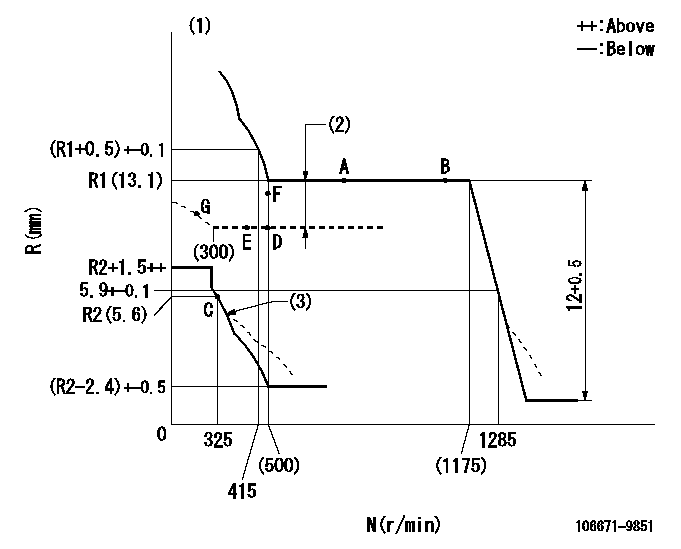
N:Pump speed
R:Rack position (mm)
(1)Deliver with positive torque control spring not operating
(2)Boost compensator stroke: BCL
(3)Damper spring setting: DL
----------
BCL=3.4+-0.1mm DL=(R2-0.2)-0.2mm
----------
----------
BCL=3.4+-0.1mm DL=(R2-0.2)-0.2mm
----------
Speed control lever angle

F:Full speed
----------
----------
a=(18deg)+-5deg
----------
----------
a=(18deg)+-5deg
0000000901
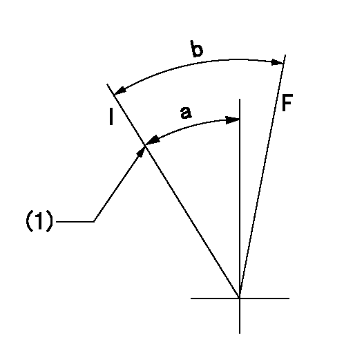
F:Full load
I:Idle
(1)Stopper bolt setting
----------
----------
a=21deg+-5deg b=(36.5deg)+-3deg
----------
----------
a=21deg+-5deg b=(36.5deg)+-3deg
Stop lever angle
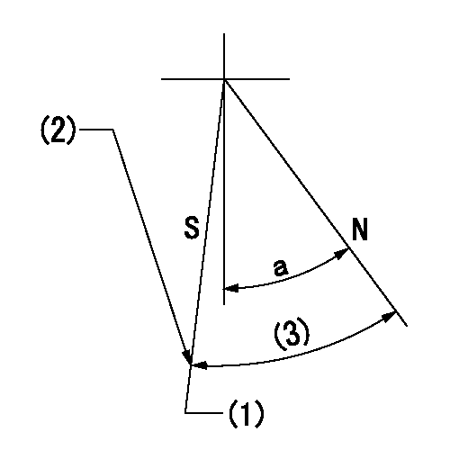
N:Pump normal
S:Stop the pump.
(1)Rack position = actual measurement
(2)Stopper bolt setting
(3)(Actual measurement)
----------
----------
a=38deg+-5deg
----------
----------
a=38deg+-5deg
Timing setting

(1)Pump vertical direction
(2)Coupling's key groove position at No 1 cylinder's beginning of injection
(3)-
(4)-
----------
----------
a=(6deg)
----------
----------
a=(6deg)
Information:
Do not operate the machine if any guards or covers are missing or inadequately secured. Personnel could be seriously injured or machine damage may occur.
Observe the safe working load limits of all lifting and blocking devices and keep a safe distance from suspended/blocked loads. Personnel may be seriously injured or killed by falling loads.
Reference Section
Refer to Service Magazine, M0082326, "Diesel Exhaust Fluid (DEF) Contamination on C4.4 Machine Engines".Refer to Service Magazine, M0096547, "Diesel Exhaust Fluid (DEF) Pump Filter Maintenance on Certain C4.4 Machine Engines".Refer to Special Instruction, M0096185, "Diesel Exhaust Fluid (DEF) Pump Diesel Contamination Test on Certain C4.4 Engines".Problem
There have been instances of returned DEF pumps that have no fault found or indicating contamination.Resolution
Complete the form below and attach to any SIMSi claim in addition to a Product Status Report (PSR) from before any troubleshooting was performed or any diagnostic codes were cleared.
Use the electronic service tool to download a PSR with Histograms.
Enter the diagnostic codes that require troubleshooting: ___
Perform the correct troubleshooting procedure for any active diagnostic codes. Refer to Troubleshooting, Diagnostic Trouble Codes.
If the troubleshooting procedure requests that the DEF is tested for contamination or concentration , record the results in Table 1 and Table 2.
For other DEF-related troubleshooting procedures, follow the applicable troubleshooting steps and record the results in Table 3.
Table 1
DEF Contamination
Step Instruction Completed Result Units
1 Perform the test procedure for DEF contamination. Refer to Systems Operation, Testing and Adjusting, Diesel Exhaust Fluid Quality - Test.
2 Compensator measurements. Refer to Special Instruction, M0096185, "Diesel Exhaust Fluid (DEF) Pump Diesel Contamination Test on Certain C4.4 Engines".
Diameter (A) mm
Length (B) mm
3 If contamination is present, confirm that DEF system has been flushed. Refer to Systems Operation, Testing and Adjusting, Diesel Exhaust Fluid Tank - Flush
Table 2
DEF Concentration
Step Instruction Completed Result Units
1 Perform the test procedure for DEF concentration. Refer to Systems Operation, Testing and Adjusting, Diesel Exhaust Fluid Quality - Test. %
2 If the DEF concentration is out of specification, confirm that the DEF tank has been drained and filled with the correct specification of DEF. Refer to Operation and Maintenance Manual, Diesel Exhaust Fluid - Fill.
Table 3
DEF Troubleshooting
Step Instruction Completed Result Units
1 Latest engine and Dosing Control Unit (DCU) software has been installed. Refer to Troubleshooting, ECM Software - Install.
2 DEF lines have been checked for restrictions.
3 DEF pump has been checked for restrictions.
4 DEF injector has been checked for restrictions.
5 DEF lines have been inspected for leaks.
6 Confirm the DEF pressure. Refer to Troubleshooting, DEF Pressure Does Not Respond. kPa
7 DEF dosing system accuracy test has been performed. Refer to Troubleshooting, Aftertreatment SCR System Dosing - Test.
8 DEF pump filter replaced.
9 "Aftertreatment System Functional Test" performed. Refer to Troubleshooting, Service Tool Features.
Have questions with 106671-9851?
Group cross 106671-9851 ZEXEL
Dpico
106671-9851
F 019 Z20 099
INJECTION-PUMP ASSEMBLY
Q
Q