Information injection-pump assembly
BOSCH
F 019 Z20 089
f019z20089
ZEXEL
106671-9571
1066719571
Rating:
Cross reference number
BOSCH
F 019 Z20 089
f019z20089
ZEXEL
106671-9571
1066719571
Zexel num
Bosch num
Firm num
Name
106671-9571
F 019 Z20 089
DPICO
INJECTION-PUMP ASSEMBLY
Q Q
Q Q
Calibration Data:
Adjustment conditions
Test oil
1404 Test oil ISO4113 or {SAEJ967d}
1404 Test oil ISO4113 or {SAEJ967d}
Test oil temperature
degC
40
40
45
Nozzle and nozzle holder
105780-8140
Bosch type code
EF8511/9A
Nozzle
105780-0000
Bosch type code
DN12SD12T
Nozzle holder
105780-2080
Bosch type code
EF8511/9
Opening pressure
MPa
17.2
Opening pressure
kgf/cm2
175
Injection pipe
Outer diameter - inner diameter - length (mm) mm 8-3-600
Outer diameter - inner diameter - length (mm) mm 8-3-600
Overflow valve
131424-4420
Overflow valve opening pressure
kPa
157
123
191
Overflow valve opening pressure
kgf/cm2
1.6
1.25
1.95
Tester oil delivery pressure
kPa
157
157
157
Tester oil delivery pressure
kgf/cm2
1.6
1.6
1.6
Direction of rotation (viewed from drive side)
Right R
Right R
Injection timing adjustment
Direction of rotation (viewed from drive side)
Right R
Right R
Injection order
1-5-3-6-
2-4
Pre-stroke
mm
4.4
4.35
4.45
Beginning of injection position
Governor side NO.1
Governor side NO.1
Difference between angles 1
Cal 1-5 deg. 60 59.5 60.5
Cal 1-5 deg. 60 59.5 60.5
Difference between angles 2
Cal 1-3 deg. 120 119.5 120.5
Cal 1-3 deg. 120 119.5 120.5
Difference between angles 3
Cal 1-6 deg. 180 179.5 180.5
Cal 1-6 deg. 180 179.5 180.5
Difference between angles 4
Cyl.1-2 deg. 240 239.5 240.5
Cyl.1-2 deg. 240 239.5 240.5
Difference between angles 5
Cal 1-4 deg. 300 299.5 300.5
Cal 1-4 deg. 300 299.5 300.5
Injection quantity adjustment
Adjusting point
-
Rack position
12.3
Pump speed
r/min
700
700
700
Each cylinder's injection qty
mm3/st.
154
150.1
157.9
Basic
*
Fixing the rack
*
Standard for adjustment of the maximum variation between cylinders
*
Injection quantity adjustment_02
Adjusting point
C
Rack position
R2(5.5)
Pump speed
r/min
325
325
325
Each cylinder's injection qty
mm3/st.
11
9.4
12.6
Fixing the rack
*
Standard for adjustment of the maximum variation between cylinders
*
Injection quantity adjustment_03
Adjusting point
A
Rack position
R1(12.3)
Pump speed
r/min
700
700
700
Average injection quantity
mm3/st.
154
153
155
Basic
*
Fixing the lever
*
Boost pressure
kPa
84
84
Boost pressure
mmHg
630
630
Injection quantity adjustment_04
Adjusting point
G
Rack position
-
Pump speed
r/min
100
100
100
Average injection quantity
mm3/st.
110
90
130
Fixing the lever
*
Boost pressure
kPa
0
0
0
Boost pressure
mmHg
0
0
0
Boost compensator adjustment
Pump speed
r/min
550
550
550
Rack position
(R3-2.5)
Boost pressure
kPa
6.7
5.4
8
Boost pressure
mmHg
50
40
60
Boost compensator adjustment_02
Pump speed
r/min
550
550
550
Rack position
R3-0.8
Boost pressure
kPa
45.3
44.6
46
Boost pressure
mmHg
340
335
345
Boost compensator adjustment_03
Pump speed
r/min
550
550
550
Rack position
R3(R1(12
.3))
Boost pressure
kPa
70.6
67.3
73.9
Boost pressure
mmHg
530
505
555
Timer adjustment
Pump speed
r/min
-
Advance angle
deg.
1.5
1
2
Load
0/4
Remarks
Measure speed (beginning of operation).
Measure speed (beginning of operation).
Timer adjustment_02
Pump speed
r/min
-
Advance angle
deg.
0
0
0
Load
0/4
Remarks
Measure the actual speed.
Measure the actual speed.
Timer adjustment_03
Pump speed
r/min
-
Advance angle
deg.
0
0
0
Load
4/4
Remarks
Measure the actual speed.
Measure the actual speed.
Timer adjustment_04
Pump speed
r/min
-
Advance angle
deg.
3.5
2.8
4
Load
4/4
Remarks
Measure the actual speed, stop
Measure the actual speed, stop
Test data Ex:
Governor adjustment
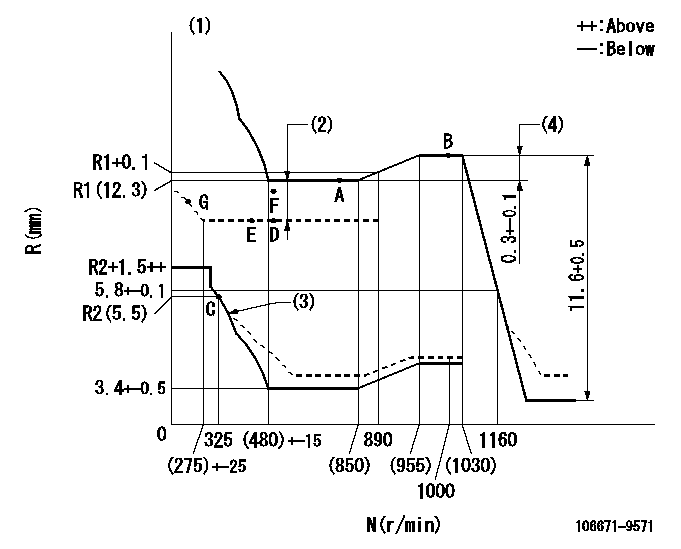
N:Pump speed
R:Rack position (mm)
(1)Tolerance for racks not indicated: +-0.05mm.
(2)Boost compensator stroke: BCL
(3)Damper spring setting: DL
(4)Rack difference between N = N1 and N = N2
----------
BCL=(2.5)+-0.1mm DL=(R2-0.2)-0.2mm N1=1000r/min N2=700r/min
----------
----------
BCL=(2.5)+-0.1mm DL=(R2-0.2)-0.2mm N1=1000r/min N2=700r/min
----------
Speed control lever angle

F:Full speed
----------
----------
a=(17.5deg)+-5deg
----------
----------
a=(17.5deg)+-5deg
0000000901
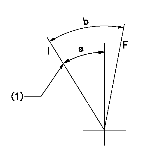
F:Full load
I:Idle
(1)Stopper bolt setting
----------
----------
a=21deg+-5deg b=33deg+-3deg
----------
----------
a=21deg+-5deg b=33deg+-3deg
Stop lever angle
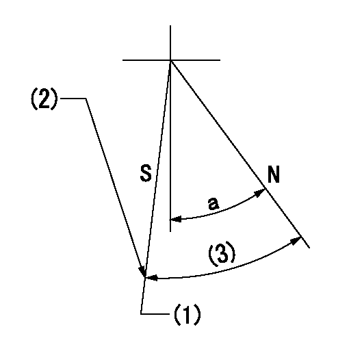
N:Pump normal
S:Stop the pump.
(1)Rack position = actual measurement
(2)Stopper bolt setting
(3)(Actual measurement)
----------
----------
a=38deg+-5deg
----------
----------
a=38deg+-5deg
Timing setting

(1)Pump vertical direction
(2)Coupling's key groove position at No 1 cylinder's beginning of injection
(3)-
(4)-
----------
----------
a=(6deg)
----------
----------
a=(6deg)
Information:
Introduction
The problem that is identified below has a known solution. Use the solution that is identified below.Problem
The procedure for the Disassembly and Assembly needs to be updated to include the information below.Solution
Do not operate or work on this product unless you have read and understood the instruction and warnings in the relevant Operation and Maintenance Manuals and relevant service literature. Failure to follow the instructions or heed the warnings could result in injury or death. Proper care is your responsibility.
Inspect the quill tubes and fuel injectors for cuts or marks at the mating surfaces.
Replace any quill tubes since the quill tubes are a one time use component. Replace the copper washer when replacing the fuel injector.
Follow the steps below for installing the quill tunes and fuel injectors.
Seat the injector by installing and torquing the injector hold down clamp bolt to 30 3 N m (22 2 lb ft).
Install the quill tube and tighten the quill nut between 15 N m (11 lb ft) to 20 N m (15 lb ft).
Apply a final torque of 30 3 N m (22 2 lb ft) to the injector hold down clamp bolt.
Apply a final torque between 50 N m (37 lb ft) to 55 N m (41 lb ft).
Have questions with 106671-9571?
Group cross 106671-9571 ZEXEL
Niigata-Urawa
Dpico
Komatsu
Mitsubishi-Heav
Dpico
106671-9571
F 019 Z20 089
INJECTION-PUMP ASSEMBLY
Q
Q