Information injection-pump assembly
BOSCH
9 400 617 045
9400617045
ZEXEL
106671-9380
1066719380
NIIGATA-URAWA
W1N47112A
w1n47112a

Rating:
Service parts 106671-9380 INJECTION-PUMP ASSEMBLY:
1.
_
7.
COUPLING PLATE
8.
_
9.
_
11.
Nozzle and Holder
12.
Open Pre:MPa(Kqf/cm2)
31.4(320)
15.
NOZZLE SET
Include in #1:
106671-9380
as INJECTION-PUMP ASSEMBLY
Cross reference number
BOSCH
9 400 617 045
9400617045
ZEXEL
106671-9380
1066719380
NIIGATA-URAWA
W1N47112A
w1n47112a
Zexel num
Bosch num
Firm num
Name
106671-9380
9 400 617 045
W1N47112A NIIGATA-URAWA
INJECTION-PUMP ASSEMBLY
DMF13HS K
DMF13HS K
Calibration Data:
Adjustment conditions
Test oil
1404 Test oil ISO4113 or {SAEJ967d}
1404 Test oil ISO4113 or {SAEJ967d}
Test oil temperature
degC
40
40
45
Nozzle and nozzle holder
105780-8250
Bosch type code
1 688 901 101
Nozzle
105780-0120
Bosch type code
1 688 901 990
Nozzle holder
105780-2190
Opening pressure
MPa
20.7
Opening pressure
kgf/cm2
211
Injection pipe
Outer diameter - inner diameter - length (mm) mm 8-3-600
Outer diameter - inner diameter - length (mm) mm 8-3-600
Overflow valve
131425-0120
Overflow valve opening pressure
kPa
157
123
191
Overflow valve opening pressure
kgf/cm2
1.6
1.25
1.95
Tester oil delivery pressure
kPa
255
255
255
Tester oil delivery pressure
kgf/cm2
2.6
2.6
2.6
Direction of rotation (viewed from drive side)
Left L
Left L
Injection timing adjustment
Direction of rotation (viewed from drive side)
Left L
Left L
Injection order
1-4-2-6-
3-5
Pre-stroke
mm
3.05
3
3.1
Beginning of injection position
Governor side NO.1
Governor side NO.1
Difference between angles 1
Cal 1-4 deg. 60 59.5 60.5
Cal 1-4 deg. 60 59.5 60.5
Difference between angles 2
Cyl.1-2 deg. 120 119.5 120.5
Cyl.1-2 deg. 120 119.5 120.5
Difference between angles 3
Cal 1-6 deg. 180 179.5 180.5
Cal 1-6 deg. 180 179.5 180.5
Difference between angles 4
Cal 1-3 deg. 240 239.5 240.5
Cal 1-3 deg. 240 239.5 240.5
Difference between angles 5
Cal 1-5 deg. 300 299.5 300.5
Cal 1-5 deg. 300 299.5 300.5
Injection quantity adjustment
Adjusting point
A
Rack position
11.3
Pump speed
r/min
900
900
900
Average injection quantity
mm3/st.
148.5
145.5
151.5
Max. variation between cylinders
%
0
-3
3
Basic
*
Fixing the lever
*
Injection quantity adjustment_02
Adjusting point
Z
Rack position
3.7+-0.5
Pump speed
r/min
500
500
500
Average injection quantity
mm3/st.
34.5
31.5
37.5
Max. variation between cylinders
%
0
-10
10
Fixing the rack
*
Injection quantity adjustment_03
Adjusting point
C
Rack position
-
Pump speed
r/min
100
100
100
Average injection quantity
mm3/st.
210
210
220
Fixing the lever
*
Rack limit
*
Timer adjustment
Pump speed
r/min
400--
Advance angle
deg.
0
0
0
Remarks
Start
Start
Timer adjustment_02
Pump speed
r/min
350
Advance angle
deg.
0.5
Timer adjustment_03
Pump speed
r/min
600
Advance angle
deg.
2
1.5
2.5
Timer adjustment_04
Pump speed
r/min
800
Advance angle
deg.
5
4.5
5.5
Remarks
Finish
Finish
Test data Ex:
Governor adjustment
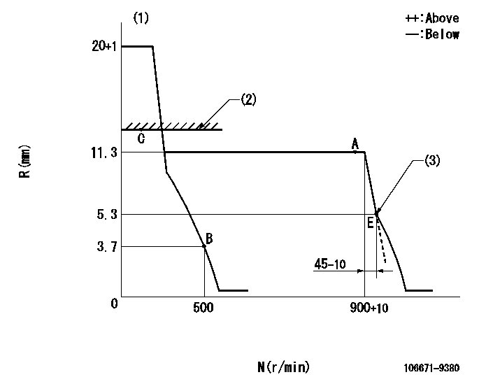
N:Pump speed
R:Rack position (mm)
(1)Target notch: K
(2)RACK LIMIT
(3)Idle sub spring setting: L1.
----------
K=14 L1=5.3-0.5mm
----------
----------
K=14 L1=5.3-0.5mm
----------
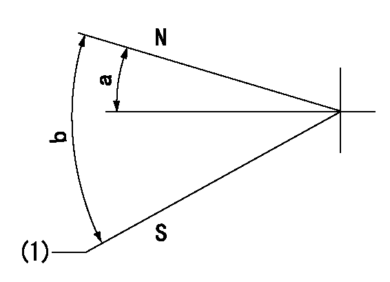
Speed control lever angle

F:Full speed
I:Idle
(1)Stopper bolt setting
----------
----------
a=19deg+-5deg b=25deg+-5deg
----------
----------
a=19deg+-5deg b=25deg+-5deg
Stop lever angle
N:Pump normal
S:Stop the pump.
(1)At delivery
----------
----------
a=30.5deg+-5deg b=53deg+-5deg
----------
----------
a=30.5deg+-5deg b=53deg+-5deg
Timing setting

(1)Pump vertical direction
(2)Coupling's key groove position at No 1 cylinder's beginning of injection
(3)-
(4)-
----------
----------
a=(6deg)
----------
----------
a=(6deg)
Information:
Personal injury can result from improper handling of chemicals.Make sure you use all the necessary protective equipment required to do the job.Make sure that you read and understand all directions and hazards described on the labels and material safety data sheet of any chemical that is used.Observe all safety precautions recommended by the chemical manufacturer for handling, storage, and disposal of chemicals.
Before servicing/performing maintenance on the machine, electrical power must be physically disconnected; battery plugs must be disconnected from the batteries, or the trailing cable must be unplugged, and warning tags and padlocks shall be applied by a certified electrician. Certified electricians shall perform or direct any electrical work, including any energized testing, repair work in controllers, motors, or other approved compartments, and shall insure that all compartments are properly closed and inspected prior to re-energization. All applicable lock out and tag out procedures must be followed.
Observe the safe working load limits of all lifting and blocking devices and keep a safe distance from suspended/blocked loads. Personnel may be seriously injured or killed by falling loads.
Connector Pin Arcing
Injector solenoid diagnostic codes can be a result of poor electrical connections between the injector and injector harness. When troubleshooting a suspected injector failure, carefully inspect injector connector pins for signs of arcing. If arcing is observed, both injector and harness must be replaced due to damaged connector pins and sockets. Connector pin arcing can also be caused by improper removal the harness from the injector. When removing the harness use approved tool 458-3562 Tool As. Refer to Illustration 2.
Illustration 2 g06300012
Connector Pin Arcing
Illustration 3 g06399136
(1) Correct placement of tool
Illustration 4 g06399157
(2) Correct removal of connectorRefer to the following publications for more details and specifications:
Refer to Troubleshooting, RENR9343, "Injector Solenoid - Test".
Refer to Service Magazine, SEPD1840, "A New Improved Removal and Installation of the Injector Harness Procedure is Now Used on Certain C13, C15, and C18 Engines".
Refer to Engine News, SEBD9957, "A New Improved Removal and Installation of the Injector Harness Procedure is Now Used on Certain C13, C15, and C18 Engines".Fuel System Restrictions
Adequate fuel flow rate through the engine is required to cool fuel injectors and injector solenoids. Contaminated fuel combined with inadequate maintenance of the secondary fuel filter can reduce fuel flow rate. Fuel filter restrictions can cause fuel to bypass internally within the secondary filter base. This bypass will allow fuel flow to return to tank without cooling the fuel injectors. Refer to Illustration 5.
Illustration 5 g06399162
(3) Normal Solenoid
(4) Overheated SolenoidTroubleshooting of injector failures should include investigation of secondary filter internal bypass. Internal bypass can be indicated by measuring fuel pressure at the sample port that is on the secondary filter base. Fuel bypass will occur as pressure approaches 655 kPa (95 psi) at the sample port. High-pressure measurements with the engine operating at low idle are especially concerning.Pressure measurement at the sample port differs from the measurement of pressure near the engine cylinder head. Pressure measured at the sample port is immediately upstream of the fuel filter element and the
Have questions with 106671-9380?
Group cross 106671-9380 ZEXEL
Dpico
Niigata-Urawa
106671-9380
9 400 617 045
W1N47112A
INJECTION-PUMP ASSEMBLY
DMF13HS
DMF13HS