Information injection-pump assembly
BOSCH
9 400 617 043
9400617043
ZEXEL
106671-9360
1066719360
NIIGATA-URAWA
W1N47102A
w1n47102a

Rating:
Service parts 106671-9360 INJECTION-PUMP ASSEMBLY:
1.
_
7.
COUPLING PLATE
8.
_
9.
_
10.
NOZZLE AND HOLDER ASSY
11.
Nozzle and Holder
12.
Open Pre:MPa(Kqf/cm2)
13.
NOZZLE-HOLDER
14.
NOZZLE
15.
NOZZLE SET
Include in #1:
106671-9360
as INJECTION-PUMP ASSEMBLY
Cross reference number
BOSCH
9 400 617 043
9400617043
ZEXEL
106671-9360
1066719360
NIIGATA-URAWA
W1N47102A
w1n47102a
Zexel num
Bosch num
Firm num
Name
106671-9360
9 400 617 043
W1N47102A NIIGATA-URAWA
INJECTION-PUMP ASSEMBLY
DMF13HS K
DMF13HS K
Calibration Data:
Adjustment conditions
Test oil
1404 Test oil ISO4113 or {SAEJ967d}
1404 Test oil ISO4113 or {SAEJ967d}
Test oil temperature
degC
40
40
45
Nozzle and nozzle holder
105780-8140
Bosch type code
EF8511/9A
Nozzle
105780-0000
Bosch type code
DN12SD12T
Nozzle holder
105780-2080
Bosch type code
EF8511/9
Opening pressure
MPa
17.2
Opening pressure
kgf/cm2
175
Injection pipe
Outer diameter - inner diameter - length (mm) mm 8-3-600
Outer diameter - inner diameter - length (mm) mm 8-3-600
Overflow valve
131425-0120
Overflow valve opening pressure
kPa
157
123
191
Overflow valve opening pressure
kgf/cm2
1.6
1.25
1.95
Tester oil delivery pressure
kPa
157
157
157
Tester oil delivery pressure
kgf/cm2
1.6
1.6
1.6
Direction of rotation (viewed from drive side)
Left L
Left L
Injection timing adjustment
Direction of rotation (viewed from drive side)
Left L
Left L
Injection order
1-4-2-6-
3-5
Pre-stroke
mm
3.05
3
3.1
Beginning of injection position
Governor side NO.1
Governor side NO.1
Difference between angles 1
Cal 1-4 deg. 60 59.5 60.5
Cal 1-4 deg. 60 59.5 60.5
Difference between angles 2
Cyl.1-2 deg. 120 119.5 120.5
Cyl.1-2 deg. 120 119.5 120.5
Difference between angles 3
Cal 1-6 deg. 180 179.5 180.5
Cal 1-6 deg. 180 179.5 180.5
Difference between angles 4
Cal 1-3 deg. 240 239.5 240.5
Cal 1-3 deg. 240 239.5 240.5
Difference between angles 5
Cal 1-5 deg. 300 299.5 300.5
Cal 1-5 deg. 300 299.5 300.5
Injection quantity adjustment
Adjusting point
A
Rack position
11.6
Pump speed
r/min
950
950
950
Average injection quantity
mm3/st.
185.5
180.5
190.5
Max. variation between cylinders
%
0
-3
3
Basic
*
Fixing the lever
*
Injection quantity adjustment_02
Adjusting point
B
Rack position
7.4+-0.5
Pump speed
r/min
250
250
250
Average injection quantity
mm3/st.
54.5
51.5
57.5
Max. variation between cylinders
%
0
-10
10
Fixing the rack
*
Timer adjustment
Pump speed
r/min
350
Advance angle
deg.
0.5
Timer adjustment_02
Pump speed
r/min
600
Advance angle
deg.
1.6
1.1
2.1
Timer adjustment_03
Pump speed
r/min
800
Advance angle
deg.
5
4.5
5.5
Remarks
Finish
Finish
Test data Ex:
Governor adjustment
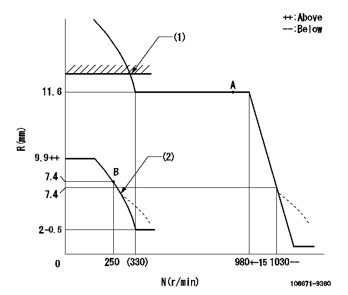
N:Pump speed
R:Rack position (mm)
(1)Rack limit using the stop lever: R1
(2)Damper spring setting: DL
----------
R1=12.6+0.2mm DL=6.9-0.3mm
----------
----------
R1=12.6+0.2mm DL=6.9-0.3mm
----------
0000000901

F:Full load
I:Idle
(1)Stopper bolt setting
----------
----------
a=13deg+-5deg b=18deg+-3deg
----------
----------
a=13deg+-5deg b=18deg+-3deg
Stop lever angle
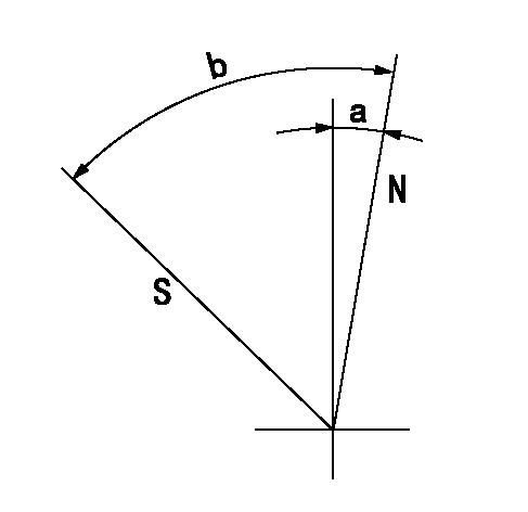
N:Pump normal
S:Stop the pump.
----------
----------
a=4deg+-5deg b=38deg+-5deg
----------
----------
a=4deg+-5deg b=38deg+-5deg
Timing setting

(1)Pump vertical direction
(2)Coupling's key groove position at No 1 cylinder's beginning of injection
(3)-
(4)-
----------
----------
a=(7deg)
----------
----------
a=(7deg)
Information:
Introduction
The problem that is identified below does not have a known permanent solution. Until a permanent solution is known, use the solution that is identified below.Problem
There have been some instances of issues with the following fuel injection pumps:
Table 1
Part Number Description
295-0435 Fuel Injection Pump Gp
348-6930 Pump
415-4313 Pump
420-4524 Fuel Injection Pump
422-5257 Fuel Injection Pump
443-3226 Fuel Injection Pump The issue may be reported as low engine power or the high idle speed may be inconsistent. Most issues have been reported below 200–300 hours of service.Solution
Note: Do not attempt to adjust the fuel pump or repair the fuel pump.Install a replacement fuel pump of the same part number. Refer to Disassembly and Assembly, Fuel Injection Pump - Remove and Disassembly and Assembly, Fuel Injection Pump - Install for the correct procedure.Retain the removed fuel pump for 30 days. The fuel pump will be requested for return using the Send It Back (SIB) process.
Have questions with 106671-9360?
Group cross 106671-9360 ZEXEL
Dpico
Niigata-Urawa
106671-9360
9 400 617 043
W1N47102A
INJECTION-PUMP ASSEMBLY
DMF13HS
DMF13HS