Information injection-pump assembly
BOSCH
9 400 611 717
9400611717
ZEXEL
106671-9190
1066719190
NIIGATA-URAWA
75L47012A
75l47012a
Rating:
Service parts 106671-9190 INJECTION-PUMP ASSEMBLY:
1.
_
7.
COUPLING PLATE
8.
_
9.
_
11.
Nozzle and Holder
12.
Open Pre:MPa(Kqf/cm2)
31.4{320}
15.
NOZZLE SET
Include in #1:
106671-9190
as INJECTION-PUMP ASSEMBLY
Cross reference number
BOSCH
9 400 611 717
9400611717
ZEXEL
106671-9190
1066719190
NIIGATA-URAWA
75L47012A
75l47012a
Zexel num
Bosch num
Firm num
Name
106671-9190
9 400 611 717
75L47012A NIIGATA-URAWA
INJECTION-PUMP ASSEMBLY
DMF13HZ K 14CA INJECTION PUMP ASSY PE6P,6PD PE
DMF13HZ K 14CA INJECTION PUMP ASSY PE6P,6PD PE
Calibration Data:
Adjustment conditions
Test oil
1404 Test oil ISO4113 or {SAEJ967d}
1404 Test oil ISO4113 or {SAEJ967d}
Test oil temperature
degC
40
40
45
Nozzle and nozzle holder
105780-8140
Bosch type code
EF8511/9A
Nozzle
105780-0000
Bosch type code
DN12SD12T
Nozzle holder
105780-2080
Bosch type code
EF8511/9
Opening pressure
MPa
17.2
Opening pressure
kgf/cm2
175
Injection pipe
Outer diameter - inner diameter - length (mm) mm 8-3-600
Outer diameter - inner diameter - length (mm) mm 8-3-600
Overflow valve
131425-0120
Overflow valve opening pressure
kPa
157
123
191
Overflow valve opening pressure
kgf/cm2
1.6
1.25
1.95
Tester oil delivery pressure
kPa
157
157
157
Tester oil delivery pressure
kgf/cm2
1.6
1.6
1.6
Direction of rotation (viewed from drive side)
Left L
Left L
Injection timing adjustment
Direction of rotation (viewed from drive side)
Left L
Left L
Injection order
1-4-2-6-
3-5
Pre-stroke
mm
3.05
3
3.1
Beginning of injection position
Governor side NO.1
Governor side NO.1
Difference between angles 1
Cal 1-4 deg. 60 59.5 60.5
Cal 1-4 deg. 60 59.5 60.5
Difference between angles 2
Cyl.1-2 deg. 120 119.5 120.5
Cyl.1-2 deg. 120 119.5 120.5
Difference between angles 3
Cal 1-6 deg. 180 179.5 180.5
Cal 1-6 deg. 180 179.5 180.5
Difference between angles 4
Cal 1-3 deg. 240 239.5 240.5
Cal 1-3 deg. 240 239.5 240.5
Difference between angles 5
Cal 1-5 deg. 300 299.5 300.5
Cal 1-5 deg. 300 299.5 300.5
Injection quantity adjustment
Adjusting point
A
Rack position
13.6
Pump speed
r/min
1000
1000
1000
Average injection quantity
mm3/st.
236
231
241
Max. variation between cylinders
%
0
-3
3
Basic
*
Fixing the lever
*
Injection quantity adjustment_02
Adjusting point
B
Rack position
5.5+-0.5
Pump speed
r/min
300
300
300
Average injection quantity
mm3/st.
17
15.5
18.5
Max. variation between cylinders
%
0
-10
10
Fixing the rack
*
Timer adjustment
Pump speed
r/min
350
Advance angle
deg.
0.5
Timer adjustment_02
Pump speed
r/min
600
Advance angle
deg.
1.6
1.1
2.1
Timer adjustment_03
Pump speed
r/min
800
Advance angle
deg.
5
4.5
5.5
Remarks
Finish
Finish
Test data Ex:
Governor adjustment
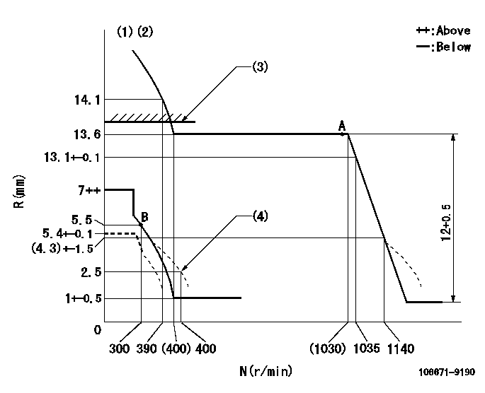
N:Pump speed
R:Rack position (mm)
(1)Tolerance for racks not indicated: +-0.05mm.
(2)Set the load lever's stop position so that R = aa (N = 0).
(3)Rack limit using the stop lever: R1
(4)Damper spring setting
----------
aa=5.4+-0.1mm R1=13.9+-0.1mm
----------
----------
aa=5.4+-0.1mm R1=13.9+-0.1mm
----------
Speed control lever angle

F:Full speed
----------
----------
a=(2.5deg)+-5deg
----------
----------
a=(2.5deg)+-5deg
0000000901
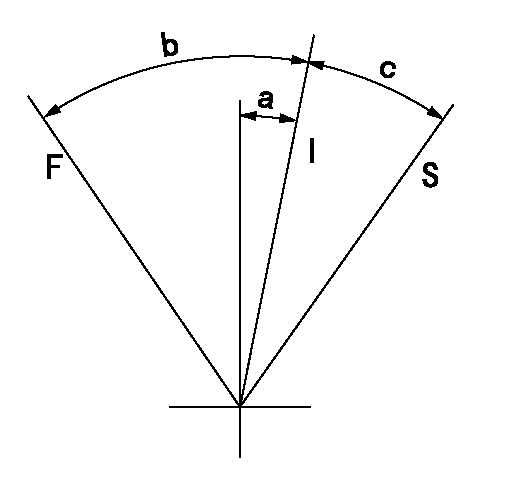
F:Full load
I:Idle
S:Stop
----------
----------
a=20deg+-5deg b=46.5deg+-3deg c=(10deg)+-5deg
----------
----------
a=20deg+-5deg b=46.5deg+-3deg c=(10deg)+-5deg
Stop lever angle
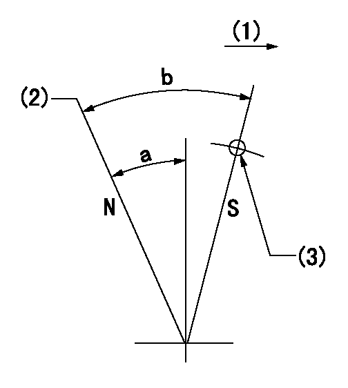
N:Pump normal
S:Stop the pump.
(1)Drive side
(2)Rack position = aa
(3)Use the hole at R = bb
----------
aa=13.9+-0.1mm bb=50mm
----------
a=34deg+-5deg b=36deg+-5deg
----------
aa=13.9+-0.1mm bb=50mm
----------
a=34deg+-5deg b=36deg+-5deg
Timing setting

(1)Pump vertical direction
(2)Coupling's key groove position at No 1 cylinder's beginning of injection
(3)-
(4)-
----------
----------
a=(6deg)
----------
----------
a=(6deg)
Information:
Illustration 2 g06542023
(T1a) Eccentric gasket
Install adjustment tool (T1) on the injector for center cylinder (2) using eccentric gasket (T1a). Install eccentric gasket (T1a) over the check valve in place of the O-ring.
Illustration 3 g06542029
(T1b) Supply fitting
(T1c) Purge hose
(T2) Inlet hose
Connect a suitable container filled with clean diesel fuel to supply fitting (T1b) using inlet hose (T2). Place a small cup under purge hose (T1c).
Illustration 4 g06536094
(1) Drive clutch side cylinder
(2) Center cylinder
(3) Alternator side cylinder
(A) TDC index mark
Rotate the engine in the direction of rotation (clockwise) until center cylinder (2) is at Top-Dead-Center (TDC) with the compression stroke. The reference mark for center cylinder (2) must be aligned with the TDC index mark (A) and the valves must be closed.
Illustration 5 g06536129
Center cylinder (2) at 11° Before-Top-Dead-Center (BTDC)
(1) Drive clutch side cylinder
(2) Center cylinder
(3) Alternator side cylinder
(A) TDC index mark
Illustration 6 g06542031
(T1c) Purge hose
Raise the fuel container above the level of the injector. Rotate the engine counterclockwise until reference mark (2) is to the left of the 11° Before-Top-Dead-Center (BTDC) mark or until fuel is observed flowing from purge hose (T1c).
Illustration 7 g06542019
(T1c) Purge hose
Rotate the engine clockwise and stop immediately when the fuel stops flowing from purge hose (T1c). The beginning of injection has been reached when the fuel stops flowing.
Illustration 8 g06536129
Center cylinder (2) rotated 11°
(1) Drive clutch side cylinder
(2) Center cylinder
(3) Alternator side cylinder
(A) TDC index mark
Observe the alignment of the reference mark for center cylinder (2) and the 11° BTDC mark.Note: If mark (2) aligns with the 11° mark, timing is correct and proceed to Step 9. If marks are not aligned, the injector timing must be adjusted. Adjust injector timing using the procedure in Step 8.
Observe the position of the reference mark for center cylinder (2) and the mark at 11° of rotation for BTDC. Note if the injector timing is early or late.Note: If the reference mark for center cylinder (2) is left of the 11° BTDC mark, injector timing is early. If the mark is to the right, injector timing is late.
Illustration 9 g06536148
(B) Jam nut
Rotate the engine to align the reference mark for center cylinder (2) and the 11° BTDC mark. Loosen jam nut (B) on the fuel injector timing adjustment screw. For late timing, proceed to Step 8b. For early timing, proceed to Step 8c
Illustration 10 g06536146
(C) Adjustment screw
Late Timing: While watching purge hose (T1c), turn adjustment screw (C) clockwise until fuel flow stops.
Early Timing: While watching purge hose (T1c), turn adjustment screw (C) counterclockwise until fuel flow starts. Then, turn adjustment screw (C) clockwise until fuel flow stops.
Hold adjustment screw (C) and tighten jam nut (B) securely. Check the injector timing by repeating Steps 5 through 7.
Remove adjustment tool (T1) and install with eccentric gasket (T1a) on the injector for drive clutch side cylinder (1). Rotate the engine 120° clockwise using the reference mark for cylinder (1). Repeat Steps 4 through 8.
Repeat Step 9 for alternator side cylinder (3).
Illustration 11 g06543249
(1) 562-0435 O-Ring Seal
Remove adjustment tool (T1) and eccentric gasket (T1a). Reinstall the fuel rail with four new
Have questions with 106671-9190?
Group cross 106671-9190 ZEXEL
Daewoo
Dpico
Hyundai
Dpico
Hyundai
Dpico
Mitsubishi-Heav
Dpico
Dpico
Niigata-Urawa
106671-9190
9 400 611 717
75L47012A
INJECTION-PUMP ASSEMBLY
DMF13HZ
DMF13HZ