Information injection-pump assembly
BOSCH
F 019 Z20 076
f019z20076
ZEXEL
106671-9185
1066719185
Rating:
Cross reference number
BOSCH
F 019 Z20 076
f019z20076
ZEXEL
106671-9185
1066719185
Zexel num
Bosch num
Firm num
Name
106671-9185
F 019 Z20 076
DPICO
INJECTION-PUMP ASSEMBLY
H100 Q
H100 Q
Calibration Data:
Adjustment conditions
Test oil
1404 Test oil ISO4113 or {SAEJ967d}
1404 Test oil ISO4113 or {SAEJ967d}
Test oil temperature
degC
40
40
45
Nozzle and nozzle holder
105780-8140
Bosch type code
EF8511/9A
Nozzle
105780-0000
Bosch type code
DN12SD12T
Nozzle holder
105780-2080
Bosch type code
EF8511/9
Opening pressure
MPa
17.2
Opening pressure
kgf/cm2
175
Injection pipe
Outer diameter - inner diameter - length (mm) mm 8-3-600
Outer diameter - inner diameter - length (mm) mm 8-3-600
Overflow valve
134424-1420
Overflow valve opening pressure
kPa
162
147
177
Overflow valve opening pressure
kgf/cm2
1.65
1.5
1.8
Tester oil delivery pressure
kPa
157
157
157
Tester oil delivery pressure
kgf/cm2
1.6
1.6
1.6
Direction of rotation (viewed from drive side)
Right R
Right R
Injection timing adjustment
Direction of rotation (viewed from drive side)
Right R
Right R
Injection order
1-4-2-6-
3-5
Pre-stroke
mm
4
3.94
4
Beginning of injection position
Drive side NO.1
Drive side NO.1
Difference between angles 1
Cal 1-4 deg. 60 59.75 60.25
Cal 1-4 deg. 60 59.75 60.25
Difference between angles 2
Cyl.1-2 deg. 120 119.75 120.25
Cyl.1-2 deg. 120 119.75 120.25
Difference between angles 3
Cal 1-6 deg. 180 179.75 180.25
Cal 1-6 deg. 180 179.75 180.25
Difference between angles 4
Cal 1-3 deg. 240 239.75 240.25
Cal 1-3 deg. 240 239.75 240.25
Difference between angles 5
Cal 1-5 deg. 300 299.75 300.25
Cal 1-5 deg. 300 299.75 300.25
Injection quantity adjustment
Adjusting point
A
Rack position
9.7
Pump speed
r/min
700
700
700
Average injection quantity
mm3/st.
130
128
132
Max. variation between cylinders
%
0
-2
2
Basic
*
Fixing the lever
*
Boost pressure
kPa
53.3
53.3
Boost pressure
mmHg
400
400
Injection quantity adjustment_02
Adjusting point
C
Rack position
6.4+-0.5
Pump speed
r/min
260
260
260
Average injection quantity
mm3/st.
11
9
13
Max. variation between cylinders
%
0
-15
15
Fixing the rack
*
Boost pressure
kPa
0
0
0
Boost pressure
mmHg
0
0
0
Injection quantity adjustment_03
Adjusting point
G
Rack position
-
Pump speed
r/min
100
100
100
Average injection quantity
mm3/st.
125
120
130
Fixing the lever
*
Boost pressure
kPa
53.3
53.3
Boost pressure
mmHg
400
400
Rack limit
*
Boost compensator adjustment
Pump speed
r/min
550
550
550
Rack position
R1(8.8)
Boost pressure
kPa
22.7
22.7
22.7
Boost pressure
mmHg
170
170
170
Boost compensator adjustment_02
Pump speed
r/min
550
550
550
Rack position
R1+0.45
Boost pressure
kPa
28.7
28
29.4
Boost pressure
mmHg
215
210
220
Boost compensator adjustment_03
Pump speed
r/min
550
550
550
Rack position
(9.7)
Boost pressure
kPa
40
40
40
Boost pressure
mmHg
300
300
300
Timer adjustment
Pump speed
r/min
800--
Advance angle
deg.
0
0
0
Remarks
Start
Start
Timer adjustment_02
Pump speed
r/min
750
Advance angle
deg.
0.5
Timer adjustment_03
Pump speed
r/min
1000
Advance angle
deg.
2.8
2.3
3.3
Remarks
Finish
Finish
Test data Ex:
Governor adjustment
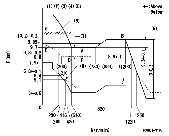
N:Pump speed
R:Rack position (mm)
(1)Lever ratio: RT
(2)Target shim dimension: TH
(3)Tolerance for racks not indicated: +-0.05mm.
(4)Boost compensator cancel stroke: BSL
(5)Set idle at point K (N = N1, R = R1) and confirm that the injection quantity does not exceed Q1 at point J (N = N2).
(6)RACK LIMIT
(7)Boost compensator stroke: BCL
(8)Damper spring setting
(9)Rack difference between N = N3 and N = N4
----------
RT=1 TH=2.1mm BSL=2.2mm N1=300r/min R1=6.4mm N2=1150r/min Q1=3mm3/st BCL=(0.9)mm N3=1150r/min N4=700r/min
----------
----------
RT=1 TH=2.1mm BSL=2.2mm N1=300r/min R1=6.4mm N2=1150r/min Q1=3mm3/st BCL=(0.9)mm N3=1150r/min N4=700r/min
----------
Speed control lever angle

F:Full speed
----------
----------
a=(7deg)+-5deg
----------
----------
a=(7deg)+-5deg
0000000901
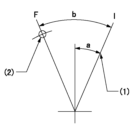
F:Full load
I:Idle
(1)Stopper bolt setting
(2)Use the hole at R = aa
----------
aa=65mm
----------
a=22deg+-5deg b=24.5deg+-3deg
----------
aa=65mm
----------
a=22deg+-5deg b=24.5deg+-3deg
Stop lever angle
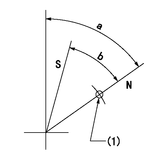
N:Pump normal
S:Stop the pump.
(1)Use the pin at R = aa
----------
aa=37mm
----------
a=64deg+-5deg b=44deg+-5deg
----------
aa=37mm
----------
a=64deg+-5deg b=44deg+-5deg
Timing setting

(1)Pump vertical direction
(2)Coupling's key groove position at No 1 cylinder's beginning of injection
(3)B.T.D.C.: aa
(4)-
----------
aa=13deg
----------
a=(50deg)
----------
aa=13deg
----------
a=(50deg)
Information:
Introduction
The problem that is identified below does not have a known permanent solution. Until a permanent solution is known, use the solution that is identified below.Problem
There have been some isolated instances of issues with the Diesel Particulate Filter (DPF) on certain C3.4B engines.Solution
Caterpillar is aware of this problem. Follow the procedure that is detailed below.
Table 1
Required Tools
Tool Part Number Part Description Qty
A 233-7191 Hose Cleaner Gp 1
Obtain a fuel sample from the engine.
Obtain a lubricating oil sample from the engine.
Attach a copy of the full service history of the engine to the Service Information Systems (SIMSi) report. Include the change history of the following components:
Engine oil
Engine oil filter
Engine fuel filter
Crankcase breather filter
Ensure that the breather element is clean and free from wear or damage. Replace the breather element. Refer to Operation and Maintenance Manual, Engine Crankcase Breather Element - Replace for the correct procedure. Ensure that the inlet hose is clean and free from restriction. If the inlet hose requires replacing, refer to Disassembly and Assembly, Crankcase Breather - Install for the correct procedure.
Determine the service hours of the engine air cleaner element. Ensure that the engine air cleaner element is clean and free from wear, damage, or restriction. If necessary, replace the engine air cleaner element. Refer to Operation and Maintenance Manual, Engine Air Cleaner Element (Single Element) - Inspect/Clean/Replace for the correct procedure. Ensure that the hose assemblies are clean and free from restriction and dust.
Inspect the inlet and outlet hoses of the turbocharger for the presence of excessive lubricating oil. If necessary, take photographs inside both inlet and outlet hoses. If necessary, take photographs inside the compressor housing for the inlet and outlet. If excessive lubricating oil is found, replace the turbocharger. Refer to Disassembly and Assembly, Turbocharger
Have questions with 106671-9185?
Group cross 106671-9185 ZEXEL
Dpico
106671-9185
F 019 Z20 076
INJECTION-PUMP ASSEMBLY
H100
H100