Information injection-pump assembly
ZEXEL
106671-9184
1066719184
Rating:
Cross reference number
ZEXEL
106671-9184
1066719184
Zexel num
Bosch num
Firm num
Name
Calibration Data:
Adjustment conditions
Test oil
1404 Test oil ISO4113 or {SAEJ967d}
1404 Test oil ISO4113 or {SAEJ967d}
Test oil temperature
degC
40
40
45
Nozzle and nozzle holder
105780-8140
Bosch type code
EF8511/9A
Nozzle
105780-0000
Bosch type code
DN12SD12T
Nozzle holder
105780-2080
Bosch type code
EF8511/9
Opening pressure
MPa
17.2
Opening pressure
kgf/cm2
175
Injection pipe
Outer diameter - inner diameter - length (mm) mm 8-3-600
Outer diameter - inner diameter - length (mm) mm 8-3-600
Overflow valve
134424-1420
Overflow valve opening pressure
kPa
162
147
177
Overflow valve opening pressure
kgf/cm2
1.65
1.5
1.8
Tester oil delivery pressure
kPa
157
157
157
Tester oil delivery pressure
kgf/cm2
1.6
1.6
1.6
Direction of rotation (viewed from drive side)
Right R
Right R
Injection timing adjustment
Direction of rotation (viewed from drive side)
Right R
Right R
Injection order
1-4-2-6-
3-5
Pre-stroke
mm
4
3.94
4
Beginning of injection position
Drive side NO.1
Drive side NO.1
Difference between angles 1
Cal 1-4 deg. 60 59.75 60.25
Cal 1-4 deg. 60 59.75 60.25
Difference between angles 2
Cyl.1-2 deg. 120 119.75 120.25
Cyl.1-2 deg. 120 119.75 120.25
Difference between angles 3
Cal 1-6 deg. 180 179.75 180.25
Cal 1-6 deg. 180 179.75 180.25
Difference between angles 4
Cal 1-3 deg. 240 239.75 240.25
Cal 1-3 deg. 240 239.75 240.25
Difference between angles 5
Cal 1-5 deg. 300 299.75 300.25
Cal 1-5 deg. 300 299.75 300.25
Injection quantity adjustment
Adjusting point
A
Rack position
9.7
Pump speed
r/min
700
700
700
Average injection quantity
mm3/st.
130
128
132
Max. variation between cylinders
%
0
-2
2
Basic
*
Fixing the lever
*
Boost pressure
kPa
53.3
53.3
Boost pressure
mmHg
400
400
Injection quantity adjustment_02
Adjusting point
C
Rack position
6.4+-0.5
Pump speed
r/min
260
260
260
Average injection quantity
mm3/st.
11
9
13
Max. variation between cylinders
%
0
-15
15
Fixing the rack
*
Boost pressure
kPa
0
0
0
Boost pressure
mmHg
0
0
0
Injection quantity adjustment_03
Adjusting point
G
Rack position
-
Pump speed
r/min
100
100
100
Average injection quantity
mm3/st.
125
120
130
Fixing the lever
*
Boost pressure
kPa
53.3
53.3
Boost pressure
mmHg
400
400
Rack limit
*
Boost compensator adjustment
Pump speed
r/min
550
550
550
Rack position
R1(8.8)
Boost pressure
kPa
22.7
22.7
22.7
Boost pressure
mmHg
170
170
170
Boost compensator adjustment_02
Pump speed
r/min
550
550
550
Rack position
R1+0.45
Boost pressure
kPa
28.7
28
29.4
Boost pressure
mmHg
215
210
220
Boost compensator adjustment_03
Pump speed
r/min
550
550
550
Rack position
(9.7)
Boost pressure
kPa
40
40
40
Boost pressure
mmHg
300
300
300
Timer adjustment
Pump speed
r/min
1000--
Advance angle
deg.
0
0
0
Remarks
Start
Start
Timer adjustment_02
Pump speed
r/min
950
Advance angle
deg.
0.5
Timer adjustment_03
Pump speed
r/min
1150
Advance angle
deg.
2
1.5
2.5
Remarks
Finish
Finish
Test data Ex:
Governor adjustment
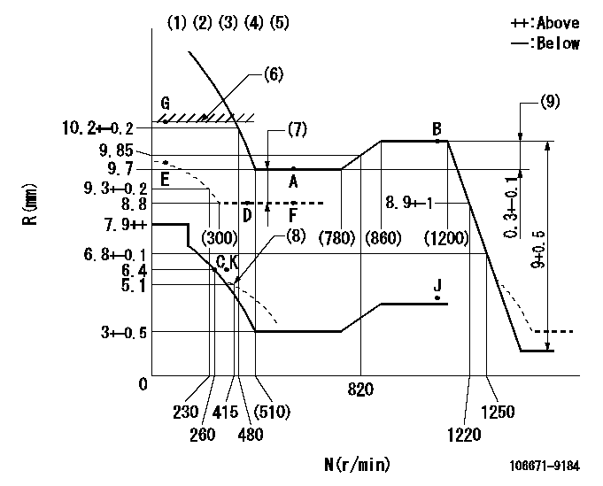
N:Pump speed
R:Rack position (mm)
(1)Lever ratio: RT
(2)Target shim dimension: TH
(3)Tolerance for racks not indicated: +-0.05mm.
(4)Boost compensator cancel stroke: BSL
(5)Set idle at point K (N = N1, R = R1) and confirm that the injection quantity does not exceed Q1 at point J (N = N2).
(6)RACK LIMIT
(7)Boost compensator stroke: BCL
(8)Damper spring setting
(9)Rack difference between N = N3 and N = N4
----------
RT=1 TH=2.1mm BSL=2.2mm N1=300r/min R1=6.4mm N2=1150r/min Q1=3mm3/st BCL=(0.9)mm N3=1150r/min N4=700r/min
----------
----------
RT=1 TH=2.1mm BSL=2.2mm N1=300r/min R1=6.4mm N2=1150r/min Q1=3mm3/st BCL=(0.9)mm N3=1150r/min N4=700r/min
----------
Speed control lever angle

F:Full speed
----------
----------
a=(7deg)+-5deg
----------
----------
a=(7deg)+-5deg
0000000901
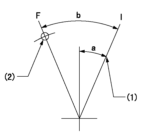
F:Full load
I:Idle
(1)Stopper bolt setting
(2)Use the hole at R = aa
----------
aa=65mm
----------
a=22deg+-5deg b=24.5deg+-3deg
----------
aa=65mm
----------
a=22deg+-5deg b=24.5deg+-3deg
Stop lever angle
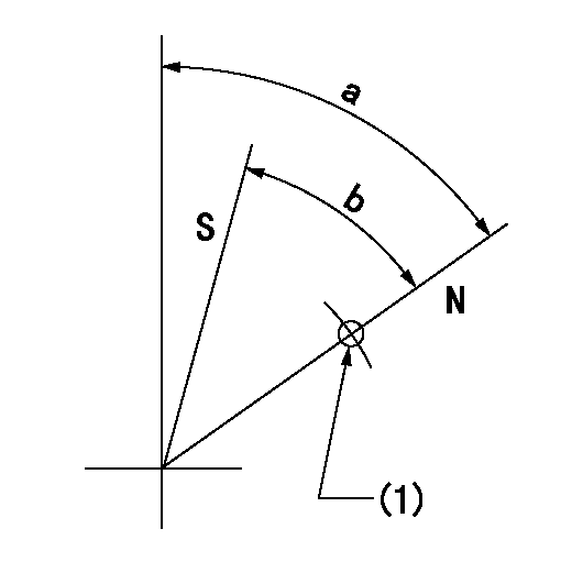
N:Pump normal
S:Stop the pump.
(1)Use the pin at R = aa
----------
aa=37mm
----------
a=64deg+-5deg b=44deg+-5deg
----------
aa=37mm
----------
a=64deg+-5deg b=44deg+-5deg
Timing setting

(1)Pump vertical direction
(2)Coupling's key groove position at No 1 cylinder's beginning of injection
(3)-
(4)-
----------
----------
a=(50deg)
----------
----------
a=(50deg)
Information:
Do not operate or work on this product unless you have read and understood the instruction and warnings in the relevant Operation and Maintenance Manuals and relevant service literature. Failure to follow the instructions or heed the warnings could result in injury or death. Proper care is your responsibility.
Illustration 1 g06531932
Typical example
(1) 310-4948 Clip
(2) 310-4947 Clip
(3) 536-7106 Grommet
Illustration 2 g06533545
Typical view of DEF lines group in 794 AC/ 796 AC/ 798 AC machines
Table 1
Required Parts
Item Qty New Part Number Part Name Former Part Number(1)
1 12(2) 310-4948 Clip 3G-8054
2 12(2) 310-4947 Clip 3G-8057
3 12(2) 536-7106 Grommet 3G-8047
(1) The former part number listed is for reference only and may differ.
(2) 785G machines require only 8 quantity.New 310-4948 Clip (1) replaces the former 3G-8054 Clip in the DEF lines group/heater lines group.New 310-4947 Clip (2) replaces the former 3G-8057 Clip in the DEF lines group/heater lines group.New 536-7106 Grommet (3) replaces the former 3G-8047 Grommet in the DEF lines group/heater lines group.