Information injection-pump assembly
BOSCH
9 400 619 455
9400619455
ZEXEL
106671-9140
1066719140

Rating:
Service parts 106671-9140 INJECTION-PUMP ASSEMBLY:
1.
_
7.
COUPLING PLATE
8.
_
9.
_
11.
Nozzle and Holder
362613-3010
12.
Open Pre:MPa(Kqf/cm2)
15.
NOZZLE SET
Include in #1:
106671-9140
as INJECTION-PUMP ASSEMBLY
Cross reference number
BOSCH
9 400 619 455
9400619455
ZEXEL
106671-9140
1066719140
Zexel num
Bosch num
Firm num
Name
Calibration Data:
Adjustment conditions
Test oil
1404 Test oil ISO4113 or {SAEJ967d}
1404 Test oil ISO4113 or {SAEJ967d}
Test oil temperature
degC
40
40
45
Nozzle and nozzle holder
105780-8140
Bosch type code
EF8511/9A
Nozzle
105780-0000
Bosch type code
DN12SD12T
Nozzle holder
105780-2080
Bosch type code
EF8511/9
Opening pressure
MPa
17.2
Opening pressure
kgf/cm2
175
Injection pipe
Outer diameter - inner diameter - length (mm) mm 8-3-600
Outer diameter - inner diameter - length (mm) mm 8-3-600
Overflow valve
131424-1520
Overflow valve opening pressure
kPa
157
123
191
Overflow valve opening pressure
kgf/cm2
1.6
1.25
1.95
Tester oil delivery pressure
kPa
157
157
157
Tester oil delivery pressure
kgf/cm2
1.6
1.6
1.6
Direction of rotation (viewed from drive side)
Right R
Right R
Injection timing adjustment
Direction of rotation (viewed from drive side)
Right R
Right R
Injection order
1-5-3-6-
2-4
Pre-stroke
mm
3.9
3.85
3.95
Beginning of injection position
Governor side NO.1
Governor side NO.1
Difference between angles 1
Cal 1-5 deg. 60 59.5 60.5
Cal 1-5 deg. 60 59.5 60.5
Difference between angles 2
Cal 1-3 deg. 120 119.5 120.5
Cal 1-3 deg. 120 119.5 120.5
Difference between angles 3
Cal 1-6 deg. 180 179.5 180.5
Cal 1-6 deg. 180 179.5 180.5
Difference between angles 4
Cyl.1-2 deg. 240 239.5 240.5
Cyl.1-2 deg. 240 239.5 240.5
Difference between angles 5
Cal 1-4 deg. 300 299.5 300.5
Cal 1-4 deg. 300 299.5 300.5
Injection quantity adjustment
Adjusting point
A
Rack position
15.5
Pump speed
r/min
900
900
900
Average injection quantity
mm3/st.
210
203
217
Max. variation between cylinders
%
0
-3
3
Basic
*
Fixing the lever
*
Boost pressure
kPa
120
120
Boost pressure
mmHg
900
900
Injection quantity adjustment_02
Adjusting point
D
Rack position
4.9+-0.5
Pump speed
r/min
450
450
450
Average injection quantity
mm3/st.
22
19
25
Fixing the rack
*
Boost pressure
kPa
0
0
0
Boost pressure
mmHg
0
0
0
Injection quantity adjustment_03
Adjusting point
E
Rack position
-
Pump speed
r/min
100
100
100
Average injection quantity
mm3/st.
320
320
340
Max. variation between cylinders
%
0
-10
10
Fixing the lever
*
Boost pressure
kPa
0
0
0
Boost pressure
mmHg
0
0
0
Rack limit
*
Boost compensator adjustment
Pump speed
r/min
500
500
500
Rack position
P1-1.6
Boost pressure
kPa
53.3
53.3
53.3
Boost pressure
mmHg
400
400
400
Boost compensator adjustment_02
Pump speed
r/min
500
500
500
Rack position
R1(16.4)
Boost pressure
kPa
107
100.3
113.7
Boost pressure
mmHg
800
750
850
Timer adjustment
Pump speed
r/min
(N1+50)-
-
Advance angle
deg.
0
0
0
Remarks
Start
Start
Timer adjustment_02
Pump speed
r/min
N1
Advance angle
deg.
0
0
0
Remarks
Measure the actual speed.
Measure the actual speed.
Timer adjustment_03
Pump speed
r/min
-
Advance angle
deg.
4
3.5
4.5
Remarks
Measure the actual speed, stop
Measure the actual speed, stop
Test data Ex:
Governor adjustment
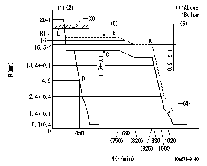
N:Pump speed
R:Rack position (mm)
(1)Target notch: K
(2)Tolerance for racks not indicated: +-0.05mm.
(3)RACK LIMIT
(4)Set idle sub-spring
(5)Boost compensator stroke
(6)Rack difference between N = N1 and N = N2
----------
K=6 N1=900r/min N2=700r/min
----------
----------
K=6 N1=900r/min N2=700r/min
----------
Speed control lever angle

F:Full speed
I:Idle
(1)Stopper bolt setting
----------
----------
a=3deg+-5deg b=20deg+-5deg
----------
----------
a=3deg+-5deg b=20deg+-5deg
Stop lever angle
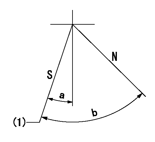
N:Pump normal
S:Stop the pump.
(1)Pump speed aa and rack position bb (to be sealed at delivery)
----------
aa=0r/min bb=1-0.2mm
----------
a=35deg+-5deg b=70deg+-5deg
----------
aa=0r/min bb=1-0.2mm
----------
a=35deg+-5deg b=70deg+-5deg
Timing setting

(1)Pump vertical direction
(2)Coupling's key groove position at No 1 cylinder's beginning of injection
(3)-
(4)-
----------
----------
a=(90deg)
----------
----------
a=(90deg)
Information:
Do not operate or work on this product unless you have read and understood the instruction and warnings in the relevant Operation and Maintenance Manuals and relevant service literature. Failure to follow the instructions or heed the warnings could result in injury or death. Proper care is your responsibility.
The following changes are adaptable to the products within the listed serial numbers, and are effective with all products after the listed serial numbers.Updating to the new components is recommended at the Planned Component Replacement (PCR) for all engines equipped with the 4x4 turbocharger configuration.
Illustration 1 g06495375
(1) New 588-3516 Support As
(D1) Oil Lubrication Jet Orifice 0.8 mm (0.032 inch)
Illustration 2 g06495382
(B) Former 525-1901 Support As
(D2) 1.6 mm (0.063 inch)The new 588-3516 Support As has an oil lubrication jet orifice that has been reduced to 0.8 mm (0.032 inch) from the jet orifice size of 1.6 mm (0.063 inch) in the former support assembly.
Illustration 3 g06495384
(2) New 582-8173 Wiring Harness
Illustration 4 g06495387
(B) Former 415-1169 Wiring HarnessThe new injector wiring harness has the closest zip tie assembly removed as shown in the illustrations above. The improved routing allows for increased harness clearance to the oil lubrication orifice.The table below contains the new part numbers for this change.
Table 1
Required Parts
Item Qty New Part Number Part Name Former Part Number
1 20 588-3516 Support As 525-1901
2 20 582-8173 Wiring Harness 415-1169 The table below contains the effective engine serial numbers for this change.
Table 2
Effective Engine Serial Numbers
S/N:4X41023-UP
S/N:L4G1032-UP